

You are using an out of date browser. It may not display this or other websites correctly.
You should upgrade or use an alternative browser.
You should upgrade or use an alternative browser.
across the bench [season-2] the electron strikes back
- Thread starter sae-7125
- Start date


sae-7125
Super Member
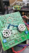
wiggle test for the bottle up front revealed some potentially woofer damaging noise so a closer inspection transpired. spray attempts failed to resolve the issue.
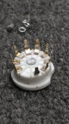
definitely cheap sockets which makes them easy to purchase and replace
quite possibly mechanical damage from the close encounter of the 4th kind, noted earlier.
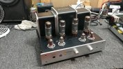


maybe modify it to have a fixed resistor from the negative end of the pot to the wiper. If the wiper then lost contact the grid goes full negative and stops flowing current rather than to zero volts and max flow.one of the pots ended up being the issue, intermittent wiper connection. adjusting the pot or any kind of physical interaction exposes the issue, dim bulb safety net makes this easy to identify.
Why mfg don't do this, or set up the pots as a shunt to ground so they fail safe absolutely baffles me but I don't know that i've ever seen a commercially designed amp with a fail safe bias setup despite being really simple to pull off.
sae-7125
Super Member
we are in the same boat on that one. seems like i bumped into one schematic that had the bias safety resistor implemented but failed to make a better note to remember the situation. definitely rare to see and easy to install.Why mfg don't do this, or set up the pots as a shunt to ground so they fail safe absolutely baffles me


sae-7125
Super Member
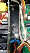
and now exhibit "b", someone spilled more magic on the inverted floor.
power supply board has some dark secrets to reveal. the domino effect put into motion by an undocumented quantum singularity of unknown origin which also has a birds eye view of the event horizon in question. particle physics chaos, patent pending.
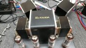

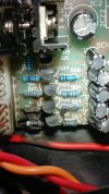

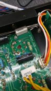

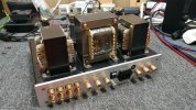
Was the area on the board near the tube sockets actually the source? I don't see anything damaged, looks more like it was deposited from elsewhere. Not sure where that fried resistor and transistor lives in relation but that seems like a possibility.
Curious what that chunk of circuit does. If its some sort of auto bias sample thing, a tube short could possibly roast things in the cathode circuit
Curious what that chunk of circuit does. If its some sort of auto bias sample thing, a tube short could possibly roast things in the cathode circuit
sae-7125
Super Member
source of the tube board smoke is the wire harness connector, upcoming photo(s) will show how things played out (human/operator error?).Was the area on the board near the tube sockets actually the source?
power supply board below the small heat sinks. which probably feeds the volume control motor circuit or something.Not sure where that fried resistor and transistor lives in relation but that seems like a possibility.
the resistors and transistors plus line of electrolytics looks like some type of bias circuit. no schematic could be found i.e. flying blind on this system.
a potential hint:
i wonder what happens when a person tries to measure bias with a dmm set to milli-amp mode?? what do you suppose happens when a large inductor with an established line of electromagantic credit is disrupted with a bank repo across ~2mm pin gap (think jacobs ladder effect).
no schematic to see, easily, if this system design has g2 resistors. looking at the board traces probably not.
either way, slowly piecing together the post-mortem diagnostic (cause of death) of this little integrated tube amp.
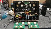
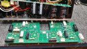
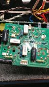
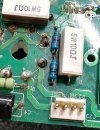
sae-7125
Super Member
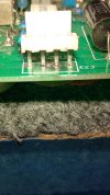
hiking up the skirt to see ground zero
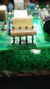
there was easily a couple mm of space between the exposed edges of the neighboring traces
just about case closed on this questionably damaged integrated amp. several uncertainties even if it were to be repaired like out-txf winding health and anything else on the board that would be weak due to kilo-volt discharge stress. since b+ is connected to the front end of the power supply circuit and b1 is downstream...