• The move to the new server is done. There are some software and database maintenance updates in process. This has us passing the hat around to help out. We appreciate any donations. Seriously, even a dollar helps. The payment page may be found here - https://www.audiokarma.org/support.html

across the bench [season-2] the electron strikes back

cj pv10a - 1.jpg
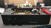
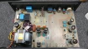
up next is a cj pv10a tube preamp

cj pv10a - 3.jpg
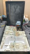
needs diagnostic and repair plus some updates and thermal adjustment. received with the top missing, current owner might already know about cj parts cooker syndrome.

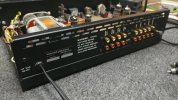
rear vent is an interesting addition although stock photos of the top cover vents are not surprising. at least there is less glassware in a larger volume cabinet vs the nuclear reactor grade pv5.
 
cj pv10a - 2.jpg
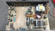
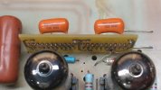
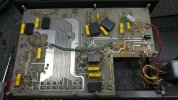
lots of mediocre grade film caps plus 3 electrolytics and an mje340 that cooks itself to death more often than not.

cj pv10a - 4.jpg
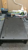
wide vent and it would appear than one chassis foot is missing
 
Not much more to do.
oddly enough there are a few things that could have been done.

this issue plagues the pv5 (early 80s) which came out a decade prior to pv10a (early 90s).

cj pv10a - 20.jpg
spoiler alert: sneak peek of future postmortem photos.

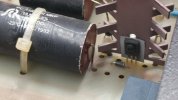
mje340 not positioned exactly where it was prior to inspection, burn mark should give a hint.
 
repair papers mention something about pv10a upgraded to pv12a.

cj pv10a - 7.jpg
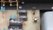
wonder if this diode addicted module is part of the 12a upgrade
 
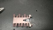
no paste and the heat sink not in full contact? tsk tsk

if thats a massive string of diodes with a bypass cap in the cathode circuit, they may be using that for tube bias in place of a resistor or whatever. Something about lower voltage zeners being quieter. Could also just be 1N4148 or similar, add enough and you get voltage drop
 
cj pv10a - 18.jpg
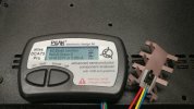
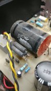
the mje340 tests as 2 diode junctions, needs to be replaced

shown factory assembled with voltage isolation pad, slightly cooked/crunchy pad like a thin crust pizza.
 
cj pv10a - 19.jpg
closer look at ground zero, this is the direct thermal contact side vs post #346 which is the "other" side.

no thermal grease just a high voltage isolation pad that might be somewhat thermally conductive even though its a little crispy.
 
cj pv10a - 10.jpg
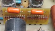
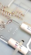
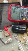
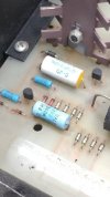
one of the "extra" caps of 150nf, in parallel with one of the 20uf main filter caps.. measures a little low, resistance.

cap pulled out of circuit, the 20uf was removed to chase which component was causing a b+ dead short. didnt bother powering up the preamp prior to dmm inspection, since there is a good chance something was out of spec.
 
silpads generally don't use thermal goop so thats probably proper. I'd prefer to see more contact area between the device and heat sink tho. Looks like it was contacting half of the transistor at best?
 
not much contact either way, i guess it shouldnt be surprising that any cj with that type of heat sink will have a self-destruction addiction.

cj pv10a - 11.jpg
one of the 20uf main/filter caps not removed yet and showing a thermal reaction of its own.

could it be the triple 5.6k 6.5w blob of power resistors... since this system received enhancements at some point in time (bumped up to 12a status or something) i wonder if the damaged cap was already damaged.

cj pv10a - 12.jpg
the 560k has a thermal reaction stripe and camped out near the x10 zeners
 
cj pv10a - 14.jpg
slowly upgrading and relocating a few components even though this chassis is much larger than the pv5 oven.

cj pv10a - 15.jpg
changed the 20uf/20uf axial filter caps to 12uf/30uf/12uf, pcb trace modz needed. the dark 30uf required some strategic drill holes for precision mounting, and all three are flat to the board. the 12uf caps are rated for 700v so having one at the front should do nicely.

at cold power-on the surge/over-voltage hits around 530v before the system starts to heat up and load down the b+.

this is just the beginning of the update/overhaul procedure. the 4uf/13.5uf axials were change to 7uf each and comfortably situated under the board.
 
cj pv10a - 21.jpg
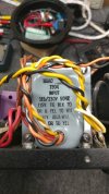
removed the 12v regulator which fees the heaters

cj pv10a - 22.jpg
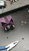
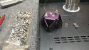
double-nut-lift-kit should help with rock crawling. have to extend the anode/cathode drive line for easier connection to the dc fuel rail.

[rock crawling options]


cj pv10a - 23.jpg
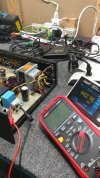
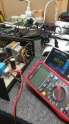
measuring front cap voltage after power-on and load becomes stable

cj pv10a - 24.jpg
voltage across second cap, looks like 59v drop across 2.2k 5w which equals 26.8ma calculation.
 
Back
Top Bottom