

You are using an out of date browser. It may not display this or other websites correctly.
You should upgrade or use an alternative browser.
You should upgrade or use an alternative browser.
across the bench [season-2] the electron strikes back
- Thread starter sae-7125
- Start date

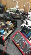
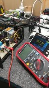

sae-7125
Super Member
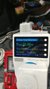
around 37w at 120v
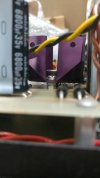
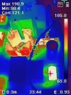
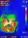
with 59v across the 2.2k there will be 22v across the back half of the crcrc which will be 375v feeding the transistor filter/regulator. not to mention lower magnitude of ripple to be filtered. the 18.2k could be bumped up to 22k or maybe as high as 33k for more aggressive b+ filtering but that will also increase heat generated. a different component was selected to replace the mje340 and its poorly designed factory heat sink.



sae-7125
Super Member
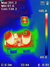
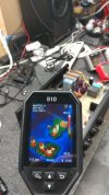
the precision resistors near the line stage bottles should be on the high wattage upgrade list. also interesting to see how hot the reed relays get just idling, room for thermal improvement perhaps.

might be able to drop that temp down to 122f/50c depending on latch voltage spec, need to find a data sheet.
sae-7125
Super Member
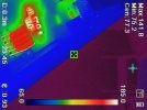
560k with the different color mid section near the 10 zeners
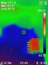
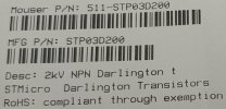
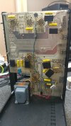
the revised heat sink using a different transistor, not another mje340. with a pv5 the heat sink hits 200f and beyond (unmodified). no idea how bad the pv10 might get since this is the first of that model number to go across the bench.
using my hand to isolate the thermal measurement since the sink temp is so low, oh the horror of being cool.
sae-7125
Super Member
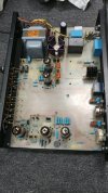
top side looks clean now
system went from x3 electrolytics down to x2 so far. i wonder just how high the heater/filament ground cap needs to be. if a 10uf film would be adequate instead of 22uf/50v. could also design a daughter card module for the 4700uf heater cap and do a low level crcrc plus a darlington filter (full film mod). should run a sim to evaluate the high current vs rc filter effect.
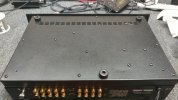
*interesting info about undocumented variations, the usual cj methodology.
sae-7125
Super Member

www.audiokarma.org/forums/threads/heathkit-w-5m-renovations-boondoggle-edition-quantum-vacuum-deep-dive.1108582/
heathkit w-5m project and analysis has reached a partial conclusion, amp 1 of 2 complete with v1.0 renovation. a long story / picture book of the design and history of a 1955 foundation piece of audio gear. more than a few options available when adjusting the system for high longevity.
since the picture book is about 90% complete it should be easy to digest for those in a hurry vs waiting for an active project to be completed. every viewer/person/bot/interstellar-hacker is different on the world wide web of digital schtuff.
sae-7125
Super Member

LSA hyperdrive 2, tube preamp plus headphone amp
www.stereotimes.com/post/lsa-hyperdrive-2-hybrid-stereo-preamplifier-headphone-amp-by-greg-voth/
*preamp shown has a different top cover
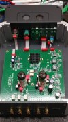
evaluating a new in box preamp, noise level and build quality.


sae-7125
Super Member
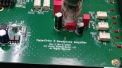
pcb version and year, also nice photo example of tube vs capacitors
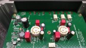
it is interesting to note that when the system is powered up and active, regardless of signal, there is a high pitch scream/whine/noise from somewhere on the board. might be one of the smt/smd inductors squawking at a modulated frequency or something.
that would explain the mostly solid top plate chassis design vs the ventilated version shown in the review link posted earlier.

sae-7125
Super Member

www.underwoodhifi.com/products/lsa-speakers
**site banner/popup**, walter's health not so good these days, schifter is recovering from a recent stroke.
verafiaudiollc.com/pages/about-us
on a somewhat sour note, i seem to have bumped into some av123 (2010) drama involving a grand jury situation.
in other news, ribbon tweeter + passive radiator = enjoyable experience. some of us tend to prefer this type of highs and lows design solution. the new-in-box LSA Statement 100 issue was not a pleasant surprise though.