• The move to the new server is done. There are some software and database maintenance updates in process. This has us passing the hat around to help out. We appreciate any donations. Seriously, even a dollar helps. The payment page may be found here - https://www.audiokarma.org/support.html

across the bench [season-2] the electron strikes back

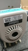
enduro em550 - 2.jpg
enduro em-550 110v 550w 0-3450rpm

i wonder if feeding one of these 120v will be an issue (170v peak vs 155v peak). seems like the dc motor is rated for 110v and after looking inside, its a very basic circuit with no mains txf. this one has no speed control although after some bench testing it now has no speed at all, double broken status?
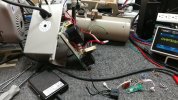
enduro em550 - 3.jpg
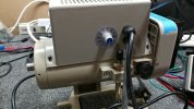
also doesnt help that the magnet mounted on the safety lock-out arm isnt positioned accurately. hall-effect module inside the tower needs some type of alignment for proper detection and motor activation.
 
enduro em550 - 4.jpg
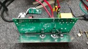
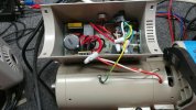
looking inside things are tight and to access the board the forward/reverse switch will need to be removed. also need to remove the magnet sense board.

enduro em550 - 5.jpg
things are getting messy with wires and carefully removing the main board.

convection cooling with no holes on the sides nor space around the pcb inside the chassis, top of plastic chassis is the only ventilation. wonder what the lifespan of these things are when used near max wattage spec.
 
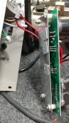
enduro em550 - 6.jpg
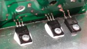
removing the board reveals a couple of outputs and a diode mounted to the large metal heat sink

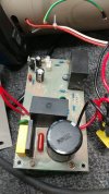
enduro em550 - 7.jpg
very basic circuit, pair of wires feeds mains ac direct to the board.

some line filtering and an mov then its into the thin package bridge rectifier and feed the big power cap (dc bus). the pair of transistor packages are igbt's. the big black mystery boxes that look like film caps are unlabeled modules. the one closest to the big power cap measures like a dc/dc converter (five pins) stepping down the dc bus to 15v and then the st-micro regulator limits things to 12v.

the other module with the bolt mount to the board commands the igbt outputs, pwm drive controller or something (10 pins). its easy to see power pins and what voltages go where to reverse engineer the system. hardest part is removing the board from the motor tower.
 
Thats why I was thinking it was a lab mixer. We have a row of them at work that have 3/8" drill chucks and a variable speed controller. The stirrers are a stainless rod with little paddle blades on them. Its used for mixing a solution of alcohol, water, and a powder in order to do viscosity testing.
 
a somewhat local regular, lots of vintage repairs over the years, takes the stock system and adds a foot pedal control plus the drill chuck and circular weight. seems to have a noticeable failure rate when new and they are stacking up. from what i diagnosed, it might be a simple fix. just a royal b-yotch to get at the board to do anything.

although no idea as to overall longevity for this type of system either way.
 
enduro em550 - 8.jpg
12v decent "quality" voltage regulator.

one of the words in the sentence above is a hint as to possible ailment and potential modus gremlin operandi for this type of machinery.

enduro em550 - 9.jpg
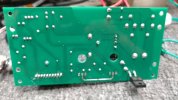
after unbolting the spacers its time to check out the only schematic for this, the board.
 
enduro em550 - 12.jpg
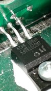
one of the originals seems to measure functional

enduro em550 - 13.jpg
the other one, not so much

need to do some specification shopping for a drop-in replacement for BOTH.
 
enduro em550 - 15.jpg
the replacement part: DGTD65T15H2TF


and now the motor spins once again and is variable as designed. that should do it for this one.

dmm measurement without removing the board could be possible, to check the igbt's for a short. there are low value resistors cross connecting a few things which might be perceived as an usually low (not shorted) resistance between transistor legs.

one potential mod, removing magnetic lock out (inside board), might be simple as creating a shorting jumper with the same connector type for a non-permanent modification. looks like the igbt controller module has a sense line thats looking for a logic low or something. didnt experiment with that option but its a possibility.
 
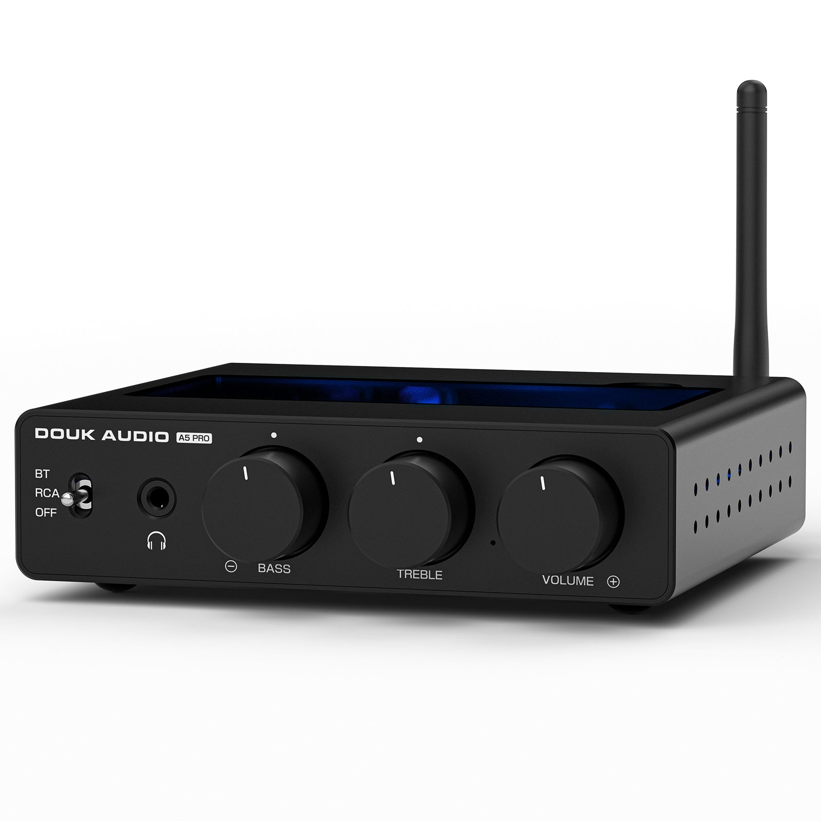
douk a5pro - 1.jpg
in less than a year the bench amp needs volume pot spray due to static and noise.

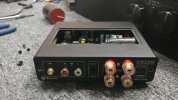
at least its easy to disassemble.

douk a5pro - 2.jpg
douk audio a5 pro

 
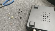
douk a5pro - 5.jpg
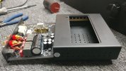
main board slides out easily, power cap next to (hugging) output inductors that get hot at idle... a deeper chassis design and relocating the cap under the board would have been better. four 1000uf in parallel would improve esr considerably, or three 2200uf just to be excessive.

douk a5pro - 6.jpg
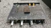
board mounted heat sink although no grease since it would be a mess to assemble and disassemble

might consider a heat sink mod like the little red amp project and possible ditch the factory chassis altogether. if so, could also do a power cap relocation and capacitance adjustment as well. add some film caps to various circuit locations.
 
douk a5pro - 9.jpg
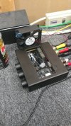
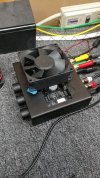
all back together, moving the power cap until a better solution is constructed. the four caps next to the op-amps might fit under the board. although they would be next to the board mounted heat sink.

douk a5pro - 10.jpg
custom cooling is still useful until the next redesign

chassis stays around room temp especially after an hour of high output exercise.
 
douk a5pro - 11.jpg
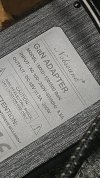
currently using the 48v 5a gallium nitride adapter which only gets slightly warm after high volume exercise.

Screenshot 2026-08-17 at 18-22-19 Douk Audio A5 PRO TPA3255 Bluetooth Amplifier HiFi Class D S...png
looks like the 48v 10a adapter helps the output numbers

would be interesting to build a film cap bank for the power brick output and see if that buffers enough to push up the dynamic response numbers. probably cheaper to buy the 10a adapter.
 
The numbers in the table that don't downright violate the laws of physics are at like 20% distortion.

The whole table can probably be safely derated by 30-40%.
 
Back
Top Bottom