• The move to the new server is done. There are some software and database maintenance updates in process. This has us passing the hat around to help out. We appreciate any donations. Seriously, even a dollar helps. The payment page may be found here - https://www.audiokarma.org/support.html

Acurus A250 and starground

Bought an LS11 preamp.... Playes good, one question though: when it sits on top of my A250 it makes hum in the speakers. I have no problem with hum with my two other Acurus preamps (L10 Ken Ealey version and my own modified L10).
Could it be the xformer in the LS11???
If I lift the LS11 form my amplifier, the hum stops in the speakers.

Best regards
 
My recommendation,
Don't sit the pre directly on top of or directly underneath an amplifier or any other piece of equipment with a transformer in it. Just because you cannot hear anything in the L10 doesn't mean its not being affected too.

A while back I was testing my Aragon 18k after working on the power supply and the distortion was worse than when I had checked it a month prior. I played with it for a while and I was trying to find out why the distortion was measuring worse than before when I realized that this time I had left the external power supply sitting on top of the 18k chassis so I moved it to the floor and the next THD+N test dropped back down to the same levels as my prior tests.
That was a lesson for me, transformers even inside of separate cases are still radiating noise so putting them directly on top or underneath your line stage is a bad idea.

I would imagine the large toroidal in the A250 is much much worse than the small 30VA transformer in my 18k power supply.
 
My recommendation,
Don't sit the pre directly on top of or directly underneath an amplifier or any other piece of equipment with a transformer in it. Just because you cannot hear anything in the L10 doesn't mean its not being affected too.

A while back I was testing my Aragon 18k after working on the power supply and the distortion was worse than when I had checked it a month prior. I played with it for a while and I was trying to find out why the distortion was measuring worse than before when I realized that this time I had left the external power supply sitting on top of the 18k chassis so I moved it to the floor and the next THD+N test dropped back down to the same levels as my prior tests.
That was a lesson for me, transformers even inside of separate cases are still radiating noise so putting them directly on top or underneath your line stage is a bad idea.

I would imagine the large toroidal in the A250 is much much worse than the small 30VA transformer in my 18k power supply.

Yes didn't have to measure anything, quite audible, low hum :(
Haven't experienced this behaviour before though, so I instantly thought that the xformer in the pre could be fault. I haven't measured it yet. Only took of the top when I bought it, looks nice and clean.

Best regards
 
Yes didn't have to measure anything, quite audible, low hum :(
Haven't experienced this behaviour before though, so I instantly thought that the xformer in the pre could be fault. I haven't measured it yet. Only took of the top when I bought it, looks nice and clean.

Best regards
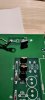
C7 wasn't connected. Don't know yet if this is the reason for the preamp being so sensitive, but it's worth a try. The leg on the cap was bended, so there has never been a solid connection or solder that attached the cap in one end.

IMG_20210216_214906.jpgIMG_20210216_214924.jpg

Regards
 
Just wanted to show my newly built LS11, and a keeper. I like the look and the double JFET added Vs the single in the L10.
As a test I decided to try 470uf and 220uf in the voltage regulator circuit instead of 1mf. There is no doubt that if I'll stick with the smaller caps, some resistors has to be adjusted. It sounds good, but to much "cream" to my liking, hence more attention is needed ;)
The xformer has also been changed, but still 5VA, the big e.caps were changed to a more reasonable 4.7mf over the stock 3.3mf.. I have a 10VA xformer sitting on hold if I decide to do this and waiting for a shipment of 6.8mf in "A"-stock quality... The 4.7mf is the easier to purchase: "B"-stock or also called "type ll" from Nichicon.... All resistors except "tape-out" are Dale's throughout the preamp. Wirewound, 60d and 55d-series.
Also tried replaced the stock yellow 10uf caps with Vishay/Roederstein. They are not "hifi" or so called pure foil ect, but wanted to find an alternative that will fit, also with the active constant current (ACC) source added to the circuit.
The hook-up wire between the added ACC is Duelund Copper/Cotton in oil. I had 2 meters in a bag after I didn't use it in my A250 years ago, so desired to use it here as it fit like a charm.
Finally I painted the knobs with professional 2K Matt black paint and clearcoat. It really looks good on this unit :)

BTW the hum when sitting on top of my A250 is still present, so C7 didn't fix this issue. I leave the preamp at one side and enjoy the music.
IMG_20210226_161043.jpg
IMG_20210225_233506.jpg
 
Last edited:
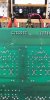
I don't suspect this connection is standard in a LS11.. There were two like this, one for each channel. They didn't fit into the schematic, so removed the "jumper" and established the connection that's been cut from R4 to R3. And the hum is gone :)

IMG_20210307_131458.jpg

Out
 
Last edited:
I have some "pops" comming from the left speaker-channel in my own A250. It been like this for some month now but lots of work has taken my time, so I haven't had enough hours on the clock to do some research until now :)

When I turn on the amp, DC-offset is always around a healthy 5mV on a cold start... And no pops....
After playing some music DC-offset raises to a very unstable ~47mV (+/-2mV, some times more) when the music is turned off and after some times the speaker will begin to make a hizz noise from the treble and a quick pop in the bass now and then. This is where I disconnect the amp ;)

I decided to put my amp under test today, but there were no oscillations to spot as high as 150kHz sinewave. I tried many different kHz to provoke at various Vpp..

But when I turned off the signal generator, the amp instantly claimed from 5mV to ~47mv DC-offset, just like when I turn off my music. I was lucky to spot this hizz/pop on the scope and my meter after about 20mim of waiting and recording with no signal at the input, the DC-offset went from 47mV to over 1000mV in a glimpse..!
I printed the o-scope results to the USB but sadly the .PNG-file is not working, so I cannot upload the results found for now :(

As soon as I turn on the signal generator again at 1/5/10/20kHz ect the DC drops instantly to rock steady 5mV!?? Only thing that had my attention was that after about 20kHz and up the DC-offset started to raise slowly and at 100kHz it was about 150mV if I remember correctly, but the sinewave is nice and clean.
-I didn't have time to try a squarewave.
-The channel don't show signs of overheating.

Any idea what is happening?

Best regards

It was a ZTX657 that was faulty.... BIAS dropped to zero and offset climbed to over 200mV no matter if a signal was applied or not. Replaced both 657's just in case, as the "hizz" became worse since my question was posted, and eventually the sound quality was highly effected, so had to pull the amp from my setup and get it fixed last evening.. All good now.

Best regards
 
Last edited:
EDIT TO THE ABOVE POSTING: ONE ZTX657 WAS OFF, BUT I DIDN'T MEANTION THAT THE POT WAS ALSO CHANGED. IT DROPED OUT FROM TIME TO TIME, AND MOST LIKELY THIS WAS THE ACTUALLY "DUE TO FAIL", AND BIAS RUNNING WILDE FROM 0mV TO 63mV!! THE POT WAS TESTED IN A FIXED SETUP AFTERWARDS WHERE IT SHOWED ITS UNSTABILITY.
DISASSEMBLING THE AMP SHOWED SOME POWERTRANSISTORS THAT'S REALLY BEEN PUSHED TO THE LIMITS.
THE POT WAS A VISHAY FOIL-TYPE, SHOWED AT PAGE 3 IN THIS THREAD AND COST ABOUT 30$ PER POT INCLUDING DANISH TAX!
-I INSTALLED A CHEAP COMMON BURNES MULTITURN TYPE AT THIS LOCATION.
 
Last edited:
I don't suspect this connection is standard in a LS11.. There were two like this, one for each channel. They didn't fit into the schematic, so removed the "jumper" and established the connection that's been cut from R4 to R3. And the hum is gone :)
View attachment 2155046

Out

Returned to these connections as posted, I've never seen an LS11 or RL11 from the bottom before this build, but the squarewave and the lack of volume surgested that these are original connections. Sorry.
I've eliminated some of the hum that came with these by applying a bit of heatshrink and some thick plastictape over the jumpers. Not entirely enough to get the hum completely gone, but the ear now has to be right at the speaker to get a feel of this, so I'll settle for now when the preamp is sitting on top of my A250
 
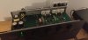
Since this thread has come to an end, I'll post a last pic of my setup so far: ACURUS A250/LS11.
I'm pleased with the sound, and fully aware that if I want more, new purchases has to be made, or fabricated manually. - who knows??

Best regards and thanks for all the help and advice here (especially @mondialfan ) // and to others; remember DIY can be a lot of fun, and a great deal of experience can be achieved in doing so. The limit is yours and yourself to discover, that's the fun part :)

IMG_20210418_175242.jpg
 
Last edited:
I don't suspect this connection is standard in a LS11.. There were two like this, one for each channel. They didn't fit into the schematic, so removed the "jumper" and established the connection that's been cut from R4 to R3. And the hum is gone :)

View attachment 2155046

Out

I've seenthat same modification from the factory on one LS11 I've upgraded. Picture attached. This was done by the factory and was the result of a screw up on the board layout. They had to cut a trace and add a ground wire to the feedback circuit. They just did a really BAD job with it. Looked like some kid with a soldering iron got loose in there.

20200530_102902.jpg
 
I've seenthat same modification from the factory on one LS11 I've upgraded. Picture attached. This was done by the factory and was the result of a screw up on the board layout. They had to cut a trace and add a ground wire to the feedback circuit. They just did a really BAD job with it. Looked like some kid with a soldering iron got loose in there.

View attachment 2201130
A post I'd never should have made:confused:, following the wrong trace on the PCB Vs schematic (R3/4) that didn't make sense at the time. I later discovered my mistake, and that is was a link from R25 to ground, so had to be factorymade.
Tried various other groundconnections to R25 resulting in a lower hum-pickup in all tests, but as soon as volume was increased the sound became compressed and a hint of noise in the top-end. This didn't show on the oscope when a single sinewave was applied.
I ended up with the original layout with jumpers in the end, as R25 has to meet inputground before going to mainground.

Regards
 
Last edited:
I'm measuring a P10 RIAA, and having some trouble with 50Hz hum on the scope. Any way to avoid this?
I tried 1/10/20kHz at various inputlevels, problem isn't solved. No load used at output
Another forum surgested an analogue scope over a digital version?

Best regards
 
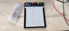
Bought my first breadboard. Should have done this a long time ago, but now it's here... It's going to fit well into my plans of testing, skipping my hard wirring for test is gonna be gooooood:)
Also bought different opamps for a DIY dc-servo. Between the bunch I think the OP37 has my attention
IMG_20210421_175041.jpgIMG_20210419_192142.jpg

Best regards
 
Does it make any sense applying an ACC-source to a P10 RIAA like in the Acurus pre's?
-It measures roughly 477μA at the resistor.
Mondial didn't opt for this in the Aragon riaa, although its more a copy/paste when you look at the P10/47k Vs the preamps from same company.

I'm restoring my old unit I've been owning for ten years now.

Best regards
 
I'm measuring a P10 RIAA, and having some trouble with 50Hz hum on the scope. Any way to avoid this?
I tried 1/10/20kHz at various inputlevels, problem isn't solved. No load used at output
Another forum surgested an analogue scope over a digital version?

Best regards

You probably need to have an isolation transformer on the scope to eliminate ground loops.
 
Said it before, but just repeat it again. Those drivers just makes the Acurus poweramplifiers even more pleasurable to listen to :)
Just finished this one, my first A250 with the new driver-transistors. I was a bit concerned about space and heat issue's with the higher railvoltage Vs the A200 gen2, but it works really well. Space is tight with the added decoupling caps ect though. C9 and C11 was bend a bit to make more room for the heatsinks on the drivers, especially near the feedback circuit this helped alot with the bigger Nichicon UES installed.
The unit shown is one of the earliest in production, nevertheless not a single scratch on the chassic after cleaning it :) a real beauty
IMG_20210430_004232.jpgIMG_20210430_154915.jpg
IMG_20210430_105624.jpg
IMG_20210430_111223.jpg

Regards
 
Last edited:
Sometimes things aren't just that easy:)
Made the first circuit of an A250 today that I bought a week ago, all good before soldering, measuring like it should and even better, but wanted to make a full restore with decoupling caps and the new drivers.
So started building, went ahead for a pre-test before installing the board in the chassic again: And absolutely nothing happened..! 16Vdc and my workbench powersupply shuts off. I always run low amps at test, as 0.3A should be more then enough to check BIAS ect at a maximum of 64Vdc that my powersupply can handle, with no signal applied that is of course according the 0.3A.

Checked all mods, diodes and resistors (only checked the new driver-transistors), resoldered every joint on the outputstage including those I haven't messed with, checked for shortcuts (several times) and 6 hours later I'm still getting a cutoff a 16Vdc at the rail where the ampers starts claiming like h.........!:rolleyes:

Although the amp is in perfect condition both inside and outside, the fuseholders were all rusty inside the clips and all of the 4 fuseclips (for the 2 fuses) broke at one board when I took the amp apart, with the fuses dangling in the chassic afterwards. This leaves me thinking that maby there is a transistor that might have bad legs from poor conditions like a garage ect, although great care is taken not to bend the old transistors when I work on these.... I simply cannot see anything else. They look ok from a visual point of view, and fully working before take apart.. So..........???:oops:
-It's late, so no more time for today but...... I really wish that I found the error before the end of the day though;)

Regards
 
Back
Top Bottom