


KNielsen
Well-Known Member
So far: haven't found anything unusual since my last post, check all transistors and they are OK. But BIAS is 90mV(!) on both NPN and PNP-powertanies at 16VDC. The BIAS-pot is set "neutral" to 0.5kohm... I cannot get pass 16VDC no matter how high I set the amps on the supply, it just run away.... Tried 0.8amp so far, still clipping hard...Sometimes things aren't just that easy
Made the first circuit of an A250 today that I bought a week ago, all good before soldering, measuring like it should and even better, but wanted to make a full restore with decoupling caps and the new drivers.
So started building, went ahead for a pre-test before installing the board in the chassic again: And absolutely nothing happened..! 16Vdc and my workbench powersupply shuts off. I always run low amps at test, as 0.3A should be more then enough to check BIAS ect at a maximum of 64Vdc that my powersupply can handle, with no signal applied that is of course according the 0.3A.
Checked all mods, diodes and resistors (only checked the new driver-transistors), resoldered every joint on the outputstage including those I haven't messed with, checked for shortcuts (several times) and 6 hours later I'm still getting a cutoff a 16Vdc at the rail where the ampers starts claiming like h.........!
Although the amp is in perfect condition both inside and outside, the fuseholders were all rusty inside the clips and all of the 4 fuseclips (for the 2 fuses) broke at one board when I took the amp apart, with the fuses dangling in the chassic afterwards. This leaves me thinking that maby there is a transistor that might have bad legs from poor conditions like a garage ect, although great care is taken not to bend the old transistors when I work on these.... I simply cannot see anything else. They look ok from a visual point of view, and fully working before take apart.. So..........???
-It's late, so no more time for today but...... I really wish that I found the error before the end of the day though
Regards


If I lower the rail VDC a bit to around 15VDC so the powersupply doesn't cutoff, I can measure increased ampers in the circuit if I touch either of the new driver-transistors or Q1/Q8....
EDIT: the Hfe is measured to around 180 on the drivers. The last amps I did was around 160Hfe
Bypassed all mods so I knew they didn't do harm, except for the 300ohm still in place in this post Vs the stock 330ohm and the new drivers.
Best regards
Last edited:
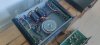
 , with the PCB taking alot of heat over the years from the ZTX, that made significant brown marks on this unit