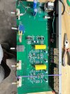
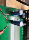
I did custom boards after seeing Mondialfan's work. But you can do this mod without adding PCB's and still make it look almost original in the original PCB.
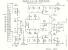
To show you a current source, look at Q3/Q4, D1-D4, R8/R9 and R15 in the Aragon 28K schematic attached.
This is your constant current sources.
Mondialfan replaced D1-D4 with single LED diodes pr rail, as do I.
I'm in Italy right now on holiday, and cannot remember the LED diodes I chose on top of my head, but;
To calculate the current:
(Vf of the diode - Vdrop of the transistor) / resistor = Current
Example (260μA target): a LED diode with a forward voltage (Vf) of 2V, a transistor with a Vdrop of typical 0.7V and we have 1.3V left.
1.3V / 5Kohm = 260μA.
The 5Kohm is R8/R9 in the 28K-schematic.
The numbers are just an example and may vary depending on components chosen!
R15 sets the current through the LED's or diodes if used. If a 20mA type LED-diode is used I normally target a 3mA for a long healthy life of the LED....
You just measure the voltage across this resistor to calculate the current passing through the LED's.
If you just want to follow the 28K-schematic with the 4x 1N4148, then R8/R9 should not be 3.92Kohm, but more something like ±3.16Kohm to get you in the ballpark of 260μA for the L10.
The Vf of the two diodes combined sets the value for calculating.
Try building a CCS on a breadboard to experiment. It's fun stuff

EDIT: do not overdo the CCS. Keep it within reason, like 250-270μA pr rail or you'll have excessive currents later on in the circuit