• The move to the new server is done. There are some software and database maintenance updates in process. This has us passing the hat around to help out. We appreciate any donations. Seriously, even a dollar helps. The payment page may be found here - https://www.audiokarma.org/support.html

Acurus L10 problem

I'm not sure. With the original pot 10 o'clock was loud. Now I think even 9 o'clock is quite high in volume.
My office is full of projects right now, so I haven't got space for testing the unit before I've cleaned the bench, but I think I need to do some plots just to see what's going on.
I have a stock Acurus P10 RIAA connected also, so I desided to try some vinyl for a change just to verify.
It was touchy too and low level music seams hard to dail in with only a few degrees on the knob to work with

It's not distorting or anything, just a bit aggressive gain

Regards
What amp?
 
What amp?
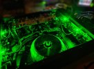
Acurus A250, completely destroyed with mods, but in good working order when tested on the oscope. Only issue is I've spotted is that the emitter resistors has drifted a lot the past year, so it might be time to install new outputs before one of them ends in magic smoke and a dead speaker... -And no wonder, I've driven the amp hard and well overbiased at +13mV and somewhere around ±92 rails for some years, pushing the small heatsinks way above "good behaviour" temperature wise.
Now (the last half year) I run it a 84V rails and 7.5mV bias just to keep things a bit safer.
IMG20231030212656~3.jpg
 
Last edited:
Thnx, I think there is a levels incompatibility somewhere. I wonder if the amp mods boosted the sensitivity. I have an L10 and haven't had that problem with the amps I've used with it.
 
Just a small update... -and thanks for the heads-up regarding line level for a follow up:
Bench cleaned so I did some test on the preamp regarding gain. The output is working just as supposed to and performed even levels throughout and no jumping or anything when turning the knob. This test was performed with different input voltages but fixed 1kHz sinewave, and I didn't see anything suspicious even at 4Vpp (2.82Vrms) that suggest "a touchy knob"...
After some fiddling with different input voltages I did some sweeps also at different volumes by turning the pot with a fixed 2.82Vrms inputsignal.
10Hz-250.000Hz was simply sweet on the oscope. Very linear(!) on both channels, tracking almost perfectly all the way and wasn't affected either by volume position.
So I'll turn my attention to the poweramp later on.

Good day:)

EDIT: I did however notice that I've installed a wrong resistor in R4 and corrected this. I did 1Kohm RN60's but I remember this should be 100ohm from factory in LS11. It's a mistake on the LS11/RL11 schematic. Regardless, the preamp meassured fine both before and after the resistor swap
 
Last edited:
By experience from my RIAA build https://www.audiokarma.org/forums/i...phono-stage-mod-rebuild.869125/#post-16923629 , I thought my LS11 could benefit form equal tweaks or at least some small adjustments. I haven't replaced my ClarityCap's though..
-This preamp has been sensitive to hum even as an original unit, and must be kept away from my A250 poweramp to keep hum in a reasonable level.
After some messing around, I desided to alter some ground points. The pads at C2/C3 is notorious to lift from the PCB if one is not very careful when desoldering old components, and I managed to lift a pad myself when first restoring this unit. Nevertheless it was resolved with a new trace to the original ground point near R27. This didn't affect the amount of hum that this unit already picked up and it continued to do so afterwards...

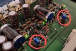
But, I tried something new last evening. Cut the track to the original ground point at C2/C3 and used solidcore copper/teflon wire and routed this as shown on the picture beneath the PCB and returned the caps ground point to R25. This has significantly reduced the interference of hum. Now it's only a small amount from the speakers, and not amplified when I put the preamp on top of my A250...

I just drew on a old pic I had on my phone as example
IMG20231002191305~2.jpg
 

Attachments

Last edited:
Thnx, I think there is a levels incompatibility somewhere. I wonder if the amp mods boosted the sensitivity. I have an L10 and haven't had that problem with the amps I've used with it.
The issue has been resolved. It was the preamp I messed up.
I bet that the 20ohm I threw in instead of the original 10ohm (R32/R33) between the PSU and the circuit was to much.
I didn't have 10ohm in my bin to return the pre to original state, but some Mills MRA05 5.6ohm and used these instead. This did raise the rail voltage a notch beyond ±18V but no biggie..
Line level works flawless again
 
Skip the DC-adjustment for now... I did it with two diodes to ground as seen in Aragon amps but connected the adjustment as seen in their preamp-series.
It's easy to adjust to 0mV, but drifts with volume. Back to the drawing board:)
 
Succes. I continued with the diode-version and ensured that they kept things stable at full offset under different voltages from my variable PSU...
Adjusted some values so maximum offset-adjustment is ±40mV maximum and connected the finished version after the inputstage. DC-Offset is not affected by the volume anymore.
Since it works I wired it up nicely:)

This could actually be fun to watch if the THD drops with offset. But I can't measure it yet....
Best regards
IMG20240212213545~2.jpgScreenshot_2024-02-12-21-31-37-66_f541918c7893c52dbd1ee5d319333948~2.jpg
 
Last edited:
To the above: matching a new diff pair is a lot easier if offset is a problem.

The internal offset after the gainstage is 26mV at worst in my LS11, so not alarming at all from the original Toshiba 970/2240.
Now it's 0-0.2mV for the fun

Regards
 
@mondialfan when i meassured the mA passing through the jfets to ensure these are kept at a reasonable level as described earlier in this thread, should I add both resistors on source and drain to get the total power dissipation they see?
I get ~130mV across each of the 25.5ohm resistors.. this equals to 5.09mA per resistor.
It's the BL-series installed, IDSS 6-12mA according to the datasheet.
I haven't touched this section and don't dare to. Just of interest if everything works and I haven't overshoot the CCS for trouble later in the circuit:)

Regards
 
Be aware that any output DC offset would be amplified by a solid state amp without DC input blocking as DC offset into the speaker load. Be certain this is not the situation with the amp to be used with the modified preamp.
 
Last edited:
@mondialfan when i measured the mA passing through the jfets to ensure these are kept at a reasonable level as described earlier in this thread, should I add both resistors on source and drain to get the total power dissipation they see?
I get ~130mV across each of the 25.5ohm resistors.. this equals to 5.09mA per resistor.
It's the BL-series installed, IDSS 6-12mA according to the datasheet.
I haven't touched this section and don't dare to. Just of interest if everything works and I haven't overshoot the CCS for trouble later in the circuit:)

Regards
Measure voltage drop from JFET source to drain on one jfet, then multiply X .00509. This is dissipation for one jfet. Then multiply that total X 2 to get total package dissipation for each JFET pair.
 
Sorry for all my sh***y writings! Sometimes I'm just to fast on the buttons, to excited to see the obvious mistakes before posting....
-Looking at the 28K-schematic it makes perfect sense why i couldn't make the offset work at first try. And why my volume-pot affected offset in the first place... Dooohhh!:(

Although I made the DC-offset pot work the preamp sounded starving in the lower notes after a few days of listening. I guess the offset function was to loosely set up, and gain ect would need attention if I were to succeed.
I reversed the thing this evening, and the schematic for my LS11 is now identical to 18K/24K with cap at the input, Zobel, Anti-parallel diodes to ground, ect...., blocking DC-offset from the pot as well;) The output caps are bypassed and should be ignored from the picture.
Values are still LS11 untill I hear the thing. Curves lookes good.
Instead of 1Mohm as per 18K/28K schematics I used a 2.21Mohm and adjusted the remaining values accordingly. I do not need that much adjustment and kept things a bit more tight then Aragon, not starving the damm thing again:)
1000003635.jpg
 
Last edited:
This is it.
Its so good sounding, and the fuzzy noise and hum I've tried to overcome ever since I bought the preamp is completely gone. The noise floor is the lowest I've heard so far from the pre's in my living room. Not a tad of hizz from the speakers at idle, nothing.
Case closed:) Acurus 11"K" :D

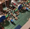
IMG20240216155043~2.jpg

PS: forget about the heatsinks on the regulators.... Had a bunch in the bin and was bored one day:D

Best regards
 
Last edited:
Be aware that any output DC offset would be amplified by a solid state amp without DC input blocking as DC offsetcinto the speaker load. Be certain this is not the situation with the amp to be used with the modified preamp.
The input of my Acurus A250 is cap free, so I'm fully aware of the danger awaiting "the brave" if a decent amount of DC slips through, and even more as I haven't any speaker protection....
With that in mind; I've been monitoring the DC at both the preamp and the poweramp intense for the last 5-6hours while playing music on/off...
The pre has settled, and sving is around ±0.5mV at normal levels. Maximum I've seen is +1.5mV, but most of the time it's around 0.2mV offset... All good!
For the poweramp I've been monitoring the dc current at the outputs while everything is hooked up to get the full aspect. I see some small "spikes" while playing loud music. Some onwards 30-50mV, but really nothing to worry about. At idle, the complete system settles precisely at around 12-13.5mV at the speaker outputs, so all good here also.
But your comment is fully legit, and I would never build a cap free amplifier for others, just for the reason you describe.

Regards
 
Small adjustment:
I matched a new diff-pair for each circuit. Its been on my mind for quite some time, and I might learn something by doing...
The obvious replacement would be On-semi 992/1845 or CDIL 970/2240. I have plenty of both in my inventory.
I desided against, and tried the On-semi BC549C/BC550C as they also has proven their quality in low noise signals.
Their HFE were better then the others, and to some degree even better then the original Toshiba I desoldered from the preamp.
I did one channel first and compared it to the original diff in the other channel on the oscope, trying to spot noise between the two, with the pre powered from my Siglent PSU. Under normal probing I couldn't seperate the 970/2240 against the 549/550. I then switched to FFT for a final tryout and both channels exceeded the limit of my oscope before differences between the two diff-sections could be established. I turned the knobs quite a bit to correct, but past -120dB the FFT couldn't calculate and just showed a straight line. I'm not an expert in this stuff, so also a fun test for me as I never did this before...
That said, the BC-series works without adjustments, and the current passing through Q5/Q6 is now almost a perfect mirror between the two channels unlike before.
I do not know where near enough about transistors, or their ability to leak or drift over time or loaded/unloaded behaviour, but DC-offset has further improved and the swing after DC-adjustment seams neglectable. Also the DC-spikes has reduced significantly when probing with signal.
I did a 10-150.000Hz sweep before leaving the bench, and its straight; as in dead straight!:)
It's to late for music here, it's way past midnight. So I'll leave this for tomorrow

Regards

 
Last edited:
Even though I wasn't able to probe differences in the diff-section, I think the overall performance has improved both technical and sound.
I finished of with a 0.22uf Wima MKP10 across the 10uf Muse at the input. After this I simply cannot hear the difference between an expensive foilcap vs the cheap alu-type.

The Sound:
Listening to the preamp it reminds me of the very best Acurus L10 build I've ever did and so much regeret selling afterwards. The sound is so relaxed without effort, natural, yet presents even the smallest details without any sharp edges.
What the L10 didn't do like this one is the immense control in the bass region. I just moved the time-constant from the frontend to the rear, but I really sounds like a breath of fresh air witch works it's way upwards in the soundstage. How big of an impact the missing cap in my Acurus A250 have on this matter I don't know. Removing the cap in the A250 did remove some tiny amount of the lowest bass, but no where near the gain and performance I'm presented with now.
I've owned the Ken Ealey-verison of this preamp witch has an extraordinary good midrange, but lack of bass. This unit can't do the mids (but really close between the two!), witch with the other improvements in this unit is so much more then I've dreamed of from an Acurus layout.

That's it:) good day AK'ers

Best regards
 
Last edited:
Back
Top Bottom