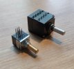
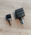
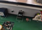
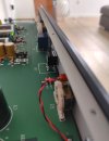
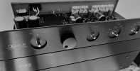
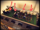
Still waiting for the new potentiometer, so continuing with some odd testing with the RC-network posted (somewhat snubber-like, but off values?! Way to high values!!)... I'm not gonna cut the traces to form a real CRC after inspection, not this unit. An external PSU would do better if I were to test a real CRC in this arrangement

I did however follow my ears regarding the improved midrange from the mystery RC-network that I cannot lookup online with "matching values" to collect it's purpose... Only my other preamp has got it that's why I'm in for a test, inspiration....
291ohm/220uf gives some feel and super detailed, but the impact is a bit to the high side in the frequency range making even minute notes a tad to clear, but not harsh.
If I calculate the same time-constant using a 470uf, the mids really starts to shine but the network adds more temperature to the transformer then normal (not alarming hot should be mentioned), and the 470uf "feels" a bit to slow compared to the 220uf. Dobling the resistor from ~170ohm to 348ohm with the same 470uf, this drops the temperature on the transformer, but most of the "musikal feel" also takes a derute thereby.
I do not have nighter 270uf or 330uf, but they are on order for later test witch might be sweet spot between heat and musical performance.
For the R as mentioned by Mondialfan in a CRC I tried raising the 10ohm resistors (R32/33, Acurus LS11) to a rough 40ohm just to get the sound experience a bit over the top. My rails are above ±18VDC so I can afford losing up til ±1volt roughly.
-At low volume with 40ohm, wow! But at higher volume things started sounding compressed, the 1000uf (C2/C3) in the PSU couldn't keep up! Back to the bench now doing 20ohm instead and the 1000uf can keep up and things sound sweet! More uf might be preferred if I'll stick with the 20ohm's. Chemi-Con KZN caps would my choice here, both 1200uf/35V and 1500uf/35V will fit the original PCB.
The 4x 0.1uf I added to the diodebridge has been removed. I couldn't hear them installed, and looking at the oscope after the regulated circuit showing a dead straight line, their purpose just added to fill. So out they go
I know there isn't any scientific writing in my post, quite opposite. Purley based on my hearing and a few measurements with my DMM and scope.
Sadly I cannot measure the impact of the RC-network that I'm working on. Most of the job is done on the back of the PCB, and I do no dare to hook it up to live 230VAC with the PCB on its back and probe around! I only measure the preamp live when it's fully installed in the chassis.
Regards