• The move to the new server is done. There are some software and database maintenance updates in process. This has us passing the hat around to help out. We appreciate any donations. Seriously, even a dollar helps. The payment page may be found here - https://www.audiokarma.org/support.html

Altec 846B Valencia restoration next steps

Thank you, I really appreciate this kind of information greatly. @RonSSNova already brought the elimination of R1 and L1 to my attention, and I'm sure I'll end up there like the rest of them. Just out of curiosity: Eliminating R1 and L1 completely should be identical with eliminating R1 and keeping L1 (shorted) in the circuit, correct?

Yes, if you eliminate R1 and simply add a wire jumper across the L1 leads ( which then shorts-out the L1 coil ) > functionally, it's the same as not including ( from the get-go ) L1 & R1.

:)
 
I don't think that this is quite the right way to do it. The 0.3 choke works in series with the 2.7 choke to provide 3.0 mH to the woofer and by-passing it will reduce this to the 2.7 value.

I think that what you should try is to remove the 8 ohm variable resistor and MOVE the connection to the 8.2 mF to the other side of the 0.3 mH choke. This way the woofer still sees 3 mH, and the 0.3 mH choke, which is removing the highs from the horn is taken out of the horn's circuit.
index.php
 
I don't think that this is quite the right way to do it. The 0.3 choke works in series with the 2.7 choke to provide 3.0 mH to the woofer and by-passing it will reduce this to the 2.7 value.

No, the 0.3mH coil hardly//barely effects the intended workings of the woofers lowpass ( because in the N1201 design this coil is either mostly bypassed or fully bypassed by the variable resistor ).

Functionally, that coil ( & variable resistor ) are included in the circuit to offer the user a choice of some HF roll-off >> "HF Trim" ( which most don't seem to use these days ).
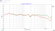
- The following pic is an approximation of the circuit: ( Green is the variable resistor "full-on > shorted" while the red trace is the variable resistor dialed to "full-off > an 8ohm value" .

FYI, Zilch moved this part ( in his Z19 rework of the M19 ) to a new location in the schematic ( making it's function a bit more obvious ).
- ( IME ) it's a feature that's more useful when dialing in a Constant Directivity type horn .

Using a 3.0mH coil instead of the stock 2.7mH coil ( in the woofer section ) would be a mistake >> this is borne out by a circuit simulation of the M19//N1201.

:)

Altec M19-N1201 _HF workings 2024-04-06 075702.png
 
Last edited:
This is all great information, thank you guys! Can’t wait to solder this thing together.

Right now I’m breaking my head apart over whether I can stick the 4 cables to the woofer and compression driver together between crossover and chassis (remember: I want to connect the external crossover to the drivers via a single 4-pole SpeakON port in the chassis), or whether I should keep them apart.
It’s one of these things where I think putting all of these together in a cable braid is probably fine, but there might be a chance they induce unwanted effects in each other?
 
There would be no issue bundling them together.
Now that said, there are audiophiles who will say it does. To the point that some split the HF and LF wiring all the way back to the power amp. It’s called bi-wiring. And requires crossovers with the LF and HF sections completely split so that each has its own input.
At that point, a guy might as well eliminate the xover all together and biamp with the xover done ahead of the power amps.
 
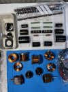
Finally have the parts I need to get started together – if work and family are kind enough I might be finished by end of this weekend.
Still need to figure out how to mount the two iron core inductors and after seeing this great YouTube video showing the audible effects of inductor alignment on crossovers I might change orientation a little, too.

IMG_8236.jpeg
 
At that point, a guy might as well eliminate the xover all together and biamp with the xover done ahead of the power amps.
I’ve actually thought about doing bi-amping with a passive crossover before two amps (one for HF one for LF) as well. There’s a nice article and schematic in Sound Practices #2 or #3 and it sounds like it might be worth pursuing.
However I haven’t seen yet a schematic for the Valencias yet. Maybe one of the regular divider networks can be adjusted to work before a power amp with the amps outputs going straight into the drivers?

Actually the decision whether I want to pursue this or not is the decisive factor in which amp I’ll build next: the same one I already have so I can bridge both into “monoblocks” to drive the Valencias, or another tube amp that doesn’t need to be identical if I end up using one for LF and the other one for HF.
Oh well, saving myself some of the fun for further down the line ;-)
 
Of course everything is taking way longer than estimated, but I’m almost done now (with one of the two crossovers). Need to make a plate for the Speakon port in the chassis and wire it up to the drivers. Also need to connect the pots to the xover.

And I wanted to build a metal cage to cover the crossovers to protect them from kiddo hands and other accidents (btw is it safe to touch the xover electronics when the speakers are running?). Don’t know if a steel cage negatively affects the inductors, though.

1D25630D-96FA-4782-A977-CD75D4D21548.jpeg
 
Last edited:
Looks really good and very well executed! To RonSSNova's comment, there should not be any safety concerns because of exposed wiring.

It appears you are pretty handy and I believe you are located in the DACH region; in case you ever have the urge to further tinker and add some "air" and a little bit high freq. extension to your Valancias, I would recommend experimenting the following DYI as described in following article (Dutch only). https://audio-creative.nl/luidsprekers/een-diy-supertweeter-van-topkwaliteit/
If you live in the DACH region, the Monacor tweeter and "Kegel" can be easily sourced locally with low shipping rates (I live in the US, had to leverage my Dutch connection to get the 120mm Kegel from Lautsprechershop Berlin). It will be a relatively cheap and simple experiment (little wood working involved).
I've made a set for my Altec M19's, they run just parallel to the compression drivers, I tried several crossover points (9KHz, 10KHz and 11KHz @ 6db slope) and settled at 11KHz. Due to the high sensitivity of the Altec compression drivers, the impact of the Kegel tweeters is not dramatic (you don't want to) but more subtle creating bit more openness and elevation of the sound stage. For me they have been keepers.
 
Last edited:
in case you ever have the urge to further tinker and add some "air" and a little bit high freq. extension to your Valancias, I would recommend experimenting the following DYI as described in following article (Dutch only). https://audio-creative.nl/luidsprekers/een-diy-supertweeter-van-topkwaliteit/

Thanks for this. I did play with the thought of adding a tweeter/super-tweeter later, but am still pushing this thought to “many months later” – gotta listen more to what I have first.
I had a look at your link and although I don’t understand Dutch (will have this translated later) it looks interesting. And it’s relatively affordable indeed.
I didn’t know this kind of “Kegel tweeter” and will have to read more about it – intuitively I would have though a more directed sound is better for imaging, but I’m sure there’s a good reason for this kind of design. So, thanks! Will keep you updated once I get to it.
 
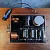
So I finished with the second crossover (at least with the part that makes it functional) an hour or so ago and tested both (only listened for 15 minutes or so). Will need more listening time tomorrow to know what I got, but the first impression is quite positive!
The effect of the HF pot is most obvious to me and I see now why most people seem to eliminate the attenuation. I don’t think I’ll want to run HF attenuated either. Less obvious are the audible effects of the MF/LF pot to me so far – I seem to mostly hear its effect on the higher frequencies, not so much the low ones.

Here’s a photo of both crossovers with the temporary pots wired up crudely.


299C5815-203B-4028-A762-5F5E110E9832.jpeg
 
Do you have a photo (or description) of how and where you mounted them on your M19s? Is the position front/back very critical in terms of the super tweeter being in/out of phase?
Please find attached a picture of the "unfinished" tweeters I made. They are just placed on top of the M19 cabinets toward the back, approximately above the point where the front of the compression driver meets the 811B horn. Exact location relative to the front/ back is not very critical, moving the tweeters several cm's back and forward does not make an audible difference.

You want to place the tweeter in phase.

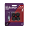
No special mounting is required, I added 3 rubber feet to the bottom of each tweeter, something like this. The rubber feet provide enough resistance and tweeters stay in place.

1716254680234.pngM19 w Kegel tweeter.jpg
 
You know how these things go: I woke up one day and found myself surrounded by two JBL2405s that I now want to connect to my Altec Valencias.

Now I’m wondering if there is a way to modify the N1201-8A network rebuild that I did (see earlier posts) to connect the 2405s to the HF section, or if I’m better off making a mini-crossover just for the 2405s connected directly to the source/speaker input?

Any suggestions or ideas from the more experienced members?
 
Gorgeous crossovers.

Lesser experience but I might be able to add some thought here. The n1201 hf circuit and how it tweaks the sound could make the tweeter harsh if it's seeing the same boost? I tried many times adding some high end above my 511 horns and the best method i found was to run the tweeter parasitic with a cap and pad. Then you won't affect the response of the other drivers at all, can add and take away as needed. Eq might be a phase 2 with its own network? It's simple but it'll help ignore many of the more complex issues of integration while you decide if it's the right path.

I recently made some z19 crossovers and the "hf" circuit there is more of a cd compensation and I would not want that on a normal tweeter. Not sure if the 1201 is really the same.
 
Thanks for your reply!

I had an inkling it wouldn't be all that straightforward, so I guess I will go with running the JBL 2405s parasitic, as you suggested.

One such way I found to connect it as a super tweeter is this:


AMP OUT (+) ––– 0.58mF –––– 4 Ohm ––––– POS (JBL 2405)
.............................................|
...........................................30 Ohm
.............................................|
AMP OUT (-) –––––––––––––––––––––––––––– NEG (JBL 2405)


Does this make sense? Maybe better to integrate an L-Pad instead of the two fixed resistors first to find the best setting?

To complicate things, I also saw solutions with a 0.1mH inductor thrown in there somewhere, for a reason I don't understand.


The n1201 hf circuit and how it tweaks the sound could make the tweeter harsh if it's seeing the same boost?
Yes, if simply connected to the HF as is it probably wouldn't work as nicely, but I thought I could maybe add an L-pad somewhere so I can attenuate the JBL 2405 separately.
Anyway, my thinking behind connecting the JBL 2405 to the HF of the N1201 was, that this way I maybe could save a part or two, make everything simpler, and have more of the signal get to the speakers without turning into heat.

 
Thanks for your reply!

I had an inkling it wouldn't be all that straightforward, so I guess I will go with running the JBL 2405s parasitic, as you suggested.

One such way I found to connect it as a super tweeter is this:


AMP OUT (+) ––– 0.58mF –––– 4 Ohm ––––– POS (JBL 2405)
.............................................|
...........................................30 Ohm
.............................................|
AMP OUT (-) –––––––––––––––––––––––––––– NEG (JBL 2405)


Does this make sense? Maybe better to integrate an L-Pad instead of the two fixed resistors first to find the best setting?

To complicate things, I also saw solutions with a 0.1mH inductor thrown in there somewhere, for a reason I don't understand.


Yes, if simply connected to the HF as is it probably wouldn't work as nicely, but I thought I could maybe add an L-pad somewhere so I can attenuate the JBL 2405 separately.
Anyway, my thinking behind connecting the JBL 2405 to the HF of the N1201 was, that this way I maybe could save a part or two, make everything simpler, and have more of the signal get to the speakers without turning into heat.
I would totally go with an lpad. If sq is the ultimate goal you can always replace it with fixed wirewound once you settle on a level. The tweeters will never see much power so you can go with the lower wattage pads. At most you'd be dissipating a few watts as your ears begin to bleed...

So if the brain is working right, just using a cap gets you a 6db filter but also a 90° phase shift. Using the inductor as well gets you a 12db filter and 180° shift; just a polarity inversion. You're not high passing the existing horn, so a long gentle slope isn't ideal imho, you want it to come in where the existing high end is dropping off and not muck up below. Those size inductors are pretty cheap so no huge outlay.
 
Back
Top Bottom