• The move to the new server is done. There are some software and database maintenance updates in process. This has us passing the hat around to help out. We appreciate any donations. Seriously, even a dollar helps. The payment page may be found here - https://www.audiokarma.org/support.html

Altec 846B Valencia restoration next steps

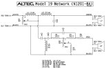
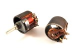
Although the MF and HF controls contain two potentiometers in each housing, only one is used per control. 35 ohm for the MF and 8 for the HF as I’m sure you noted.
Ok wait, I just re-read this and am confused: Doesn’t the schematic have it the other way round, 8 ohm for LF and 35 for HF? 8 ohm ones are much easier to find so that would be great.

you can eliminate the HF control as you will set it to max anyway.
Does setting it to max then mean that I put a 35 ohm (fixed) resistor in instead of the variable one, or no resistor at all?
 
You only use one side of the lpad in each case, so it acts as a variable resistor. Pay attention to the connection numbers shown on the schematic when you wire them up.
Great tip, thanks! Very smart.

You might consider PartsExpress for your L-Pad.
Ok great this is looking good, thanks. Also made me go back to the schematic and notice that I need a 8 ohm one, which is much easier to find than a 35 ohm one.
 
N1201-8A.jpg

Sorry to be slow to respond.
In the schematic, the 8 ohm pot controls the HF. The MAX position labeled there is max for the pot. However, it's min for the HF level.
In the max HF level, you are shorting the .3mH choke. Remember, a choke passes LF and attenuates HF. So if the desire is to eliminate the HF adjustment, you can just eliminate that choke and the pot.
The 35 ohm pot works the opposite. Remember, in the factory there are two pots in the same housing that go in opposite directions.
So set to 35 ohms is minimum reduction in the MF. Set to 0 ohms, is the max MF reduction.
 
Sorry to be slow to respond.
Oh please, no, I am beyond grateful that you—and all of you—are sacrificing a slice of your time to post here and provide me (and hopefully others, eventually) with so much knowledge. I am learning so much that I didn't pick up in my research, so thank you!

I feel like I understand this crossover schematic better now in terms of how the pots control HF and MF.
In concrete terms this means that I DO need to find a 35 ohm pot/l-pad/rheostat somewhere after all, whereas I can get rid of the 8 ohm one (and the .3 inductor) – correct?

I'm still facing the elephant-in-the-room question that I didn't dare to ask because I hoped it would become obvious to me eventually (it didn't), though: Why can I eliminate the HF attenuation and why do I not want/need to attenuate HF? I suspect it does have some fixed attenuation in the circuit (because otherwise the horn would be way louder than the dome?), but wouldn't I still want to be able to fine-tune it?
 
I’ve had my model 19’s for many years and have never had the need to turn down the HF control.

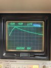
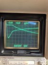
These horns are not flat out to 20khz. If you look up the response they roll off past 10khz. In fact, they aren’t flat at all over the whole range. The MF control attenuates the mids from 1.2khz up in order to match the woofer level in that freq range.

Attached are network analyzer measurements I made on these with the MF control at max, min, and my preferred setting. These are the electrical response simply loaded with 8 ohm resistors.
 

Attachments

  • IMG_1200.jpeg
    IMG_1200.jpeg
    78.3 KB · Views: 16
  • IMG_1199.jpeg
    IMG_1199.jpeg
    86.2 KB · Views: 16
  • IMG_1198.jpeg
    IMG_1198.jpeg
    94.3 KB · Views: 16
Attached are network analyzer measurements I made on these with the MF control at max, min, and my preferred setting. These are the electrical response simply loaded with 8 ohm resistors.

This is very interesting and educational – thank you for sharing!

In the meanwhile I've found few affordable 35 ohm pots and narrowed my choices down to:

- 25 ohm 7W one, if necessary with a fixed 10 ohm resistor in series to get to 35 ohm. Just as a temporary solution to find a satisfying fixed value to put in instead
25ohm7W.png

- 35 ohm 15W wirewound rheostats. Not sure if they are that good either so, again, maybe just as a temporary solution to find a fixed resistor value
35ohm15W.jpg
 
I finished making the “cushions” that substitute the disintegrated glass wool damping around the horn lips. As described previously, they are made from sound absorbing foam and acoustically transparent cloth.

IMG_7694.jpeg


At the moment I'm in the process of sanding and priming the woofer boards for repainting them.
 
A few prettification updates! I've spent the last weeks sanding, priming, oiling, waxing, painting, varnishing and am getting to a point where I'm satisfied with what I got.
There are still a few things I want to change (like adding proper metal threads into the chassis so I won't need to use the wood screws for attaching the woofer board to it anymore – taking the board on and off frequently is starting to leave nasty traces) and add (either stands/a base of some sort, or something that hides the particle board the wheels are screwed on).
Also need to finish making the grills.
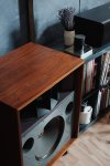
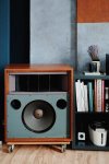
I'll spare you all the in-process shots and videos – you can see that if you look for #altec7188 on instagram if you're on it and interested – but here are two photos of the way the speakers look right now.
Almost gathered all the pieces to build new crossovers, too, so this will be the next BIG step.

HF2403X1676_VSCO.jpg
HF2403X1692_VSCO.jpg
 
Looking good! Did you make any progress on the X-Overs?

Not yet! Got most parts, but still waiting for the inductors. Should be shipped next week.
Will use the 8 Ohm pots from my HPM-60 crossovers first, just to try it out, then probably get rid of the HF attenuation as you suggested. Still figuring out minor details like whether I want to keep the crossovers outside the chassis or not (probably yes for now), and how to connect them to the horn and woofers (probably Speakon).

I just bought a pair of 846B myself. In good shape, all stock.

Exciting!! Any plans for these yet or are you gonna listen to them as they came?
 
Very good. I look forward to your impressions.

I just got these yesterday. Answered an ad on Craigslist, and it turned out that it was a good audio friend of mine. Too funny. So I got an extra good deal.
I’m just going to clean them up and listen as is. They will be replacing a pair of Santanas.
Then of course do the Xovers.
Should be fun!
 
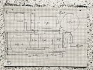
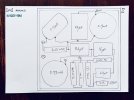
Happy Easter to all concerned! Thinking about a physical layout for the N1201-8A crossover while waiting for the parts to arrive. I made a paper puzzle with all components at actual size and moved things around until I thought I was getting somewhere.
Trying to minimize connection lengths for point-to-point soldering. Also trying to leave space to substitute the variable resistors with fixed ones later.
I’ve transferred schematics to physical layouts for my tube amp build, but never for a crossover, so if you see me doing something stupid please stop me ;-)

IMG_8122.jpeg
 
Thanks guys – wish I could start, but still waiting for some parts. Things move slow over here, sorry!
In the meanwhile I've reworked the wiring layout again and made it a little more compact and rotated the .33mH inductor 45 deg because everything is closer together now. The size of the board is now 200 x 200mm (7.9" x 7.9" I believe). But I might revert to the bigger one if I find a functional reason for it.

IMG_8172.jpeg
 
You might be okay with the current layout ... regarding your coil placements & orientation in case you decide to change, some food for thought:
Thank you – yeah it should be the same like with how you align transformers, right?

Since space isn't as much of an issue, I'll probably go back to the bigger board layout in post #93, but rotate the upper left inductor a little to shoot diagonally across the board rather than straight at the 2.7mH inductor. Just to be safe.
 
@holger7188

You might want to check with other users ( and their use of the N1201-8a with Valencias ) but it's my impression that most seem to run their horn drive circuits full out & then pull down the midrange to balance out the sound. Doing so, offers-up the most HF//UHF output.

If you find yourself doing similar, then the .33mH coil has been taken out of the circuit ( bypassed by the horn-drive, 8R variable resistor being effectively set to 0.0R ).

Both those components could then be eliminated from your final build ( again,, if R1 is wide-open.

Additionally, one can squeak a bit more HF out of the circuit by reducing the 3 ohm resistor ( R6 ) to as little as zero ( & then again, adjusting R3, the midrange variable pot. for best balance ).

- Thought-you-should-have some options.

:)
 
Last edited:
You might want to check with other users ( and their use of the N1201-8a with Valencias ) but it's my impression that most seem to run their horn drive circuits full out & then pull down the midrange to balance out the sound. Doing so, offers-up the most HF//UHF output.

If you find yourself doing similar, then the .33mH coil has been taken out of the circuit ( bypassed by the horn-drive, 8R variable resistor being effectively set to 0.0R ).

Both those components could then be eliminated from your final build ( again,, if R1 is wide-open.

Additionally, one can squeak a bit more HF out of the circuit by reducing the 3 ohm resistor ( R6 ) to as little as zero ( & then again, adjusting R3, the midrange variable pot. for best balance ).

Thank you, I really appreciate this kind of information greatly. @RonSSNova already brought the elimination of R1 and L1 to my attention, and I'm sure I'll end up there like the rest of them. Just out of curiosity: Eliminating R1 and L1 completely should be identical with eliminating R1 and keeping L1 (shorted) in the circuit, correct?

Reducing the 3 ohm resistor to squeak out more HF is completely news to me and I will certainly try that! I've decided to keep the crossovers outside of the chassis for the time being, so playing around with modifications should be easy and convenient enough.

It also seems like my inductors are finally wound and shipped with an ETA of beginning next week – so hopefully I can get my hands dirty soon :)
 
Back
Top Bottom