• The move to the new server is done. There are some software and database maintenance updates in process. This has us passing the hat around to help out. We appreciate any donations. Seriously, even a dollar helps. The payment page may be found here - https://www.audiokarma.org/support.html

B&K ST-140 RECAP BOM

Well now, we got ourselves a House Party here! :) Thanks to everyone for weighing in.
I should have been more precise jose, you're correct that the channels are separate, so point well taken. But they are related through the power supply, since there is only one transformer, and the caps, which strangely appear to be in series, distribute DC to each side. I noticed when biasing the amp previously, that a tweak on one side, had an effect on the other, so I had to adjust both "back and forth" to get things to balance. But this is quibling, I should be able to isolate the channels from one another for DC offset. I'll let you know what I read in the testing.

greg, I'm not an authority on LED specifications, but if you stick to a red LED of the same physical size as the original, you'll likely be OK, since the circuit operates at only 62 V. Unfortunately the original spec is not available to my knowledge, but I would guess modern ones are more broadly capable.

ray, pace yourself with the popcorn, this could take a while! :)

jrh
 
repositioned bridge rectifier to the case and the temp has dropped to 72.5 deg. fah. after 11/2 hours at 120v, from a high of 87+/-. shunt cap replaced .01uf /1400v.
reinstalled both 10,000uf caps in parallel(again).
to my ears, sounds pretty good.
those old can caps should definitely go bye bye.
 

Attachments

  • IMG_20200929_170505.jpg
    IMG_20200929_170505.jpg
    81.4 KB · Views: 54
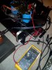
ST-140 update here - Testing an isolated left side board is all good. Thanks for the pointers jose, it seems to be dialed in. See attached photo.
Next stop - doing the same to the right side. If I get both in the "ballpark" so to speak, I'll then do the B&K recommended procedure. Thanks all!

jrh
 

Attachments

Hello JR
This is great news! You show some 17mV before adjusting it. Now You may adjust it to see if it dos indeed adjust, and next, check how close to zero can you get.
If you could also slowly bring up to 200mA of current passing through the negative rail is a very good sign. All this was with a dim bulb tester in series or was it with full mains? If you adjust this with the dim bulb in place expect some deviation when you plug it on full mains.

EDIT:
Sorry, i missed the sign in the picture were you stated that you can set the DC offset without problems. :thumbsup:
 
Comments about setting bias on 140 and 202.
I am limited to checking the bias without a signal generator and a dummy load. All I can do is take a fuse out and measure. Will this be good enough? Is so, then why the procedure that B&K provides?
Answer that guys!
 
Thanks for the picture Harley. Looks like you're getting there.
I set my bias without a signal generator and a dummy load...hooked up a pair of cheap speakers.
gradually raise the variac from 0 and gradually adjust the pots. With a thermometer, monitor the MOSFETs to not surpass 95 -100 deg. fah. of course, remove the fuse on the appropriate rail. disconnecting one board's cable connector while adjusting the other, is a pretty good way to go. replacing old components with new ones insures a rapid success.
Jose' has a good idea to short the inputs and eliminate the signal generator.
This is a lot of feedback received on this unit. Hope it serves others.
 
Last edited:
Hi, Greg, JR and Ray:
In my opinion the bare minimum to do this adjustment is a DVM.If you have two, it would be better because you can look at current and DC offset simultaneously when you power it up.. The signal generator -in my opinion- is not necessary, unless you want to see the waveform at the output with an oscilloscope.
The thermometer idea seems good, but one should keep in mind that the temperature of a heat sink mounted transistor rises quite a lot more slowly than the actual junction inside of the transistor. Thus, by the time your thermometer says 100 degrees, the junction may be on the edge of frying. But if you have a thermometer, by all means monitor the temperature.
Jose' has a good idea to short the outputs and eliminate the signal generator.

One important issue, to prevent misunderstandings, I meant to short the input (at the RCA connector). Please make sure that the output is never shorted because this will destroy the power transistors.
 
Hi, Greg, JR and Ray:
In my opinion the bare minimum to do this adjustment is a DVM.If you have two, it would be better because you can look at current and DC offset simultaneously when you power it up.. The signal generator -in my opinion- is not necessary, unless you want to see the waveform at the output with an oscilloscope.
The thermometer idea seems good, but one should keep in mind that the temperature of a heat sink mounted transistor rises quite a lot more slowly than the actual junction inside of the transistor. Thus, by the time your thermometer says 100 degrees, the junction may be on the edge of frying. But if you have a thermometer, by all means monitor the temperature.


One important issue, to prevent misunderstandings, I meant to short the input (at the RCA connector). Please make sure that the output is never shorted because this will destroy the power transistors.
I dont think that I will short anything. Sounds dangerous!
 
Yes this subject has been discussed in this forum,but a humbe summary is this:
Phono inputs are very high gain, some accept voltages of less than one millivolt, and you get some tens of volts on the output to the speakers. This means that the overall gain of the preamp, and the power stage is tens of thousands. Hum noise is common on these inputs when left unconnected because the small currents induced in the wiring inside the amplifier at 50Hz and 100 Hz due to the high mains voltage can easily reach a micro-Volt or so at these inputs which results in audible hum on the speakers. This is interference noise, and it is not limmited to 50Hz. There is a broad spectrum of noise coming from various sources. Hiss is another story, and it may originate at the phono input circuit itself.
Shorting the input of high sensitivity phono inputs is some times done from design of the amplifier, (via installation of self-shorting RCA connectors) for preventing audible interference noise to appear at the speakers. I know that the Sansui AU-919 has such feature but there are many others.
when the user switches to unconnected inputs.
 
NOOOOOOO!!! :) Too funny guys. I just finished correcting an email issue on the PC, so I hadn't been following this for a few. When I saw rays "slip-o-the-tongue" comment about shorting the outputs, I'm like, screamin' at the monitor. Good on you for correcting the record jose. Input, Output, whatever, it's all the same right? :). This stuff is very tricky ray, I do that kind of thing all the time, so I get it.Very entertaining conversation guys.

Anyway, preliminary run up on the right board of the ST-140 looked promising, but it got late on me yesterday and I only brought things up to about 75 V AC on the variac, but the readings and adjustments were behaving as they should. I'll finish tonight on this portion with a little luck.

As always, I really appreciate all the comments, it's been a big help.

jrh
 
Hey greg, some thoughts on your set-up:
If you wanted to try and do the B&K procedure,I think you could so without a lot of hassle or expense. Like ray suggested, you could use an 8 ohm speaker as a load. I wouldn't use my best speakers to do that, but if you had to, you could pick up a pair of 8 ohm computer speakers at GoodWill for next to nothing and use those for your load, or maybe you have an old set lying around. As for the signal generator, I'm pretty sure you can download free apps for your phone that could produce a suitable tone. The signal generator I'm using these days is one I picked up at a Ham Radio swapmeet for $20. If you've never checked one out, they're pretty interesting.

I believe that the B&K procedure is intended to test the system in a more comprehensive manner - under load, and at the upper limits of the audio spectrum, (20 kHZ). I'm certain there is a more technically precise reason that could be outlined, but that's over my pay grade. As mentioned earlier, I did notice that adjusting one side had a small effect on the other side, which I had to go back and forth on, almost like tuning IF transformers on a radio. Finally, doing the B&K procedure almost requires two meters. I suppose it could be done without a second meter, but boy would that be tedious. If this project is a "one-off" for you, then I'd still go to Harbor Freight and by a $5 mini meter to use as my second set of "eyes". But as jose and ray have suggested, you can get good results without doing it that way.

jrh
 
I have 2 meters now. The one I just got from Amazon has a transistor checker where you plug the transistor into the correct holes.
I will probably just do the simple adjustments without signal and load.
 
I have 2 meters now. The one I just got from Amazon has a transistor checker where you plug the transistor into the correct holes.
I will probably just do the simple adjustments without signal and load.
Good luck friend, and enjoy the new Meter!

jrh
 
yes, the inputs. replaced 3 calipers on my car today- not up to working on anything else today.
even without the 20 hz signal, the bias can be set. my unorthodox procedure and my amp rocking, proves that point.
i verified the bias setting per b k procedure(minus signal)and the setting was under by a few.
harbor freight at times gives out those dmm with purchase or coupon, found on their site.
Those little Chinese everything testers are fantastic for figuring out the pins on transistors cbe and just about everything else. And they're cheap.
just use a variac to safeguard those MOSFETs. they get hot in a flash!
 

Attachments

  • IMG_20200930_223250.jpg
    IMG_20200930_223250.jpg
    113.1 KB · Views: 35
Last edited:
ST-140 fan boys, update here.
Que the forlorn trombone - nwah, nwah. Not good. But not the end of the world either.
Bringing the right board up to 90 V AC was so far, so good last night. Current was at 160 mA, offset was a bit high at 117 mV but it all seemed good.Then, in an instant, it got away from me. Popped R9. Yep, she let out the magic smoke. Damn this circuit is unforgiving! Tonight I'll replace R9, which was interestingly one of the resistors I hadn't replaced already. Friday night I'll try to bring things up again. Fortunately, on the right side, R9 is right up top, so I can replace it in-situ without removing the board. I'm still not 100% sure that there's not a problem of some sort with the right board, but I'm still going to try and bring it into balance again tomorrow. I still feel like things are moving in a positive direction, even as I burn resistors up! :)

jrh
 
Hi JR,
I am sorry about his set back. R9 is supposed to be a 66.5 Ohms and it is passing some 18 mA if I understand the circuit correctly. Check Q9, Q10, and the two gate resistors.
Let me tell you that I have tested the adjustment procedure on a prototype that I built by copying the schematic for the ST-140. I could adjust the idle current as well as the DC offset without problems, without signal generator, without dummy load. I just used two DVM, but this may just as well be done with only one.

I built my prototype with things I had laying around, scavenged some parts from junk PCBs. I only tested it with +/-36V. because i do not have a suitable transformer to generate +/-62v. I can confirm that after I adjusted the idle current to 100mA on the negative fuse, and adjusted the DC offset to some 10 mV, i tested it with speakers and I could play music on it. Sounds all right considering my crude prototype.
 
Retried bias adjustment last night on both channels:
no 20hz signal, 8 ohm speaker, pre amp connected to amp's inputs, powered off.
disconnected/ adjusted one channel at a time. waited 10 min can caps to drain before adjusting next channel.
gradually raised the variac about every 4 min. about 10 v, or when dmm reading stabilized.
adjusted to about 15-20 mA at each 10v rise. offset not monitored.
dmm set to A dc and red terminal plugged into 300 mA dmm socket.
Set bias. No problems on either channel. Jammed today.
Jose'. !Nitido! Can you post a picture?
 
Back
Top Bottom