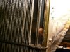
That is indeed an example of the cast epoxy transducer type that was used in the 2's and 3's. Be careful with the stators, though, they are brittle and easily broken. These can probably be rebuilt if necessary, but unless the diaphragms are torn, they are probably fine. Were you getting any sound out of them? Did you plug them into a mains supply for a couple of minutes before you tried to listen to them?


You are using an out of date browser. It may not display this or other websites correctly.
You should upgrade or use an alternative browser.
You should upgrade or use an alternative browser.
Beveridge Model 5 - Restore
- Thread starter Audio Fan
- Start date

aidynphoenix
Super Member

Another thought. Did the original owner know (and more importantly, tell you) what the correct hook-up for single amp use is? I ask because, given the number of speaker binding posts provided, jumpers across some combination of them may be necessary. I would ask the other model 5 owner you have been in communication with what his terminal/fuse layout looks like -- you may not have any electronic or transducer problems with these speakers at all.

Audio Fan
YT Channel - https://tinyurl.com/29zytwu9
Another thought. Did the original owner know (and more importantly, tell you) what the correct hook-up for single amp use is? I ask because, given the number of speaker binding posts provided, jumpers across some combination of them may be necessary. I would ask the other model 5 owner you have been in communication with what his terminal/fuse layout looks like -- you may not have any electronic or transducer problems with these speakers at all.
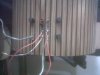
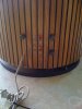
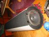
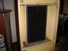
Not really, because most of the posts were snapped off some years ago, he really was not sure. Secondly, it looks like both speakers are setup differently anyway, so I need to take a close look at the internal connections. Here is a pic of each speaker.
The previous owner attached the wires so he could hook them up for a test. I've not tried hooking them up again, so it very well could be they just were not hooked up correctly from the start. :scratch2:
I have to go out of town early tomorrow morning for a trip, so will probably have to wait until the weekend, so stay tuned!

Attachments
Last edited:
Unfortunately, it seems that no two Beveridge "systems" even of the same type were identical, except for the very early ones made by Harold. Evidently, running changes were constantly being made and documentation is very poor or lost to time. Perhaps, when you get a chance, you can draw out a schematic and we can figure out what goes where.
Audio Fan
YT Channel - https://tinyurl.com/29zytwu9
That is indeed an example of the cast epoxy transducer type that was used in the 2's and 3's. Be careful with the stators, though, they are brittle and easily broken. These can probably be rebuilt if necessary, but unless the diaphragms are torn, they are probably fine. Were you getting any sound out of them? Did you plug them into a mains supply for a couple of minutes before you tried to listen to them?
Some of the "louvers" are missing on the backside, about 10 or so. I assume they should still work? The diaphragms themselves look just fine though. I could not see any tears at all.
There was only some faint sound coming from them at about half volume on the amp the previous owner was using. When I say faint, I mean you REALLY had to put your ear up close to hear anything. Also, he said to get that, he had to leave the amp on for a while. That is all the testing that has been done, thus far.
The "louvers" make up the stators and, since you have broken ones, be sure that none of the pieces have fallen into the gap between the stator and the diaphragm. If there is anything even somewhat conductive touching both the stator and diaphragm, there will be a huge breakdown in the voltage potential between the two and the transducers will not work properly if at all. You need to check them very carefully with a flashlight.
You did have these plugged into a wall socket for awhile before you tried them, right?
You did have these plugged into a wall socket for awhile before you tried them, right?
Audio Fan
YT Channel - https://tinyurl.com/29zytwu9
The "louvers" make up the stators and, since you have broken ones, be sure that none of the pieces have fallen into the gap between the stator and the diaphragm. If there is anything even somewhat conductive touching both the stator and diaphragm, there will be a huge breakdown in the voltage potential between the two and the transducers will not work properly if at all. You need to check them very carefully with a flashlight.
You did have these plugged into a wall socket for awhile before you tried them, right?
I'll take a careful look at them before hooking them back up again. I do not know how long they were plugged in prior, the previous owner really did all the testing without me there, so I cannot say for sure how anything was done. I had been talking to him via phone/email and did not see anything first hand (although I had offered) until I went to pick them up. At that point, he turned on his amp to let me hear the faint sound coming from the panel, we agreed on a price, unhooked them and I brought them home. Since then, I've not hooked them up again because I wanted to take a look at the internals first to make sure I would not create more damage.
Some additional information. I sent an email to the other Model 5 owner to ask what kind of connections are on his set. He says he has only two sets of binding posts, one for the panel and one for the woofer. HOWEVER, he has a switch that allows the internal crossover to be used or to bypass it with an external crossover. So apparently, my early set does not have the switch, but instead just used two sets of terminals. Oh how some labels would have been a nice feature. :sigh:
Yeah, Beveridge was never a big one for providing much useful support information -- was a pretty good marketing guy/inventor though.
Just a thought (again), but considering these use the System 3 transducer construction, perhaps they also use the System 3 binding post scheme. I don't know any, but maybe you can track down a System 3 owner and ask how his are connected/jumped?
Just a thought (again), but considering these use the System 3 transducer construction, perhaps they also use the System 3 binding post scheme. I don't know any, but maybe you can track down a System 3 owner and ask how his are connected/jumped?


Hi,
Joining in on this interesting thread
Audio Fan, that is the first Mod 5 with epoxy-panels I've seen.
I thought all were circuit board type like mine.
Did you check the connections wire/stator, wire/diaphragm yet?
The 3 - 3,5 nF I mentioned earlier is for the pcb-type panel, I'm
not sure what value your panels should have.
Maybe Mr Google has the answer?
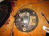
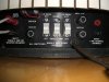
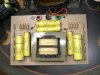
Posting some pictures of the crossover, switchpanel and som other.
Also posting a patent of the panel that might be interesting to read.
Regards
335*
Joining in on this interesting thread
Audio Fan, that is the first Mod 5 with epoxy-panels I've seen.
I thought all were circuit board type like mine.
Did you check the connections wire/stator, wire/diaphragm yet?
The 3 - 3,5 nF I mentioned earlier is for the pcb-type panel, I'm
not sure what value your panels should have.
Maybe Mr Google has the answer?
Posting some pictures of the crossover, switchpanel and som other.
Also posting a patent of the panel that might be interesting to read.
Regards
335*
Attachments

Audio Fan
YT Channel - https://tinyurl.com/29zytwu9
Ossi!! Welcome to AK! I think you will really enjoy it here, a LOT of great audio enthusiasts here to share our wonderful hobby.
Yes, I see your Model 5's are much more developed, Beveridge even started including some labels! :thmbsp:
Mine have to be a VERY early model because even Rick Beveridge mentions the Model 5's as having only used the circuit board type panel. My guess is that the circuit board design was probably still being finalized for some period of time, but they went ahead and created some Model 5's using their old panel designs to get the sales rolling. These are quite a bit smaller than the 3's, so they were most likely banking on better margins for them.
In any case, so little published information exists for any Beveridge speaker, I've not been able to locate something as specific as measurement details. That is one big reason why I wanted to document as much as possible in this thread.
"Did you check the connections wire/stator, wire/diaphragm yet?" Do you mean did I try to measure the capacitance or did I check to see that they were securely connected?
Yes, I see your Model 5's are much more developed, Beveridge even started including some labels! :thmbsp:
Mine have to be a VERY early model because even Rick Beveridge mentions the Model 5's as having only used the circuit board type panel. My guess is that the circuit board design was probably still being finalized for some period of time, but they went ahead and created some Model 5's using their old panel designs to get the sales rolling. These are quite a bit smaller than the 3's, so they were most likely banking on better margins for them.
In any case, so little published information exists for any Beveridge speaker, I've not been able to locate something as specific as measurement details. That is one big reason why I wanted to document as much as possible in this thread.
"Did you check the connections wire/stator, wire/diaphragm yet?" Do you mean did I try to measure the capacitance or did I check to see that they were securely connected?

My pair of 2's were in the 100 to 110 serial number range, iirc, and Rick Beveridge told me that they were towards the end of the "pure" System 2 run. He also has said that the later 2SW and variants were the most popular ones, so I guess at least 120 pairs of the original OTL amplified systems were made. I have never seen production figures for the subsequent models.
Attachments


Thank you
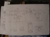
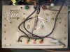
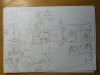
Here is some more, "home-made" so there could be some errors
I didn't note the component-values on the schematic but it gives a general idea of the thing.
It is for the later model 5
Here is some more, "home-made" so there could be some errors
I didn't note the component-values on the schematic but it gives a general idea of the thing.
It is for the later model 5
Attachments
Audio Fan
YT Channel - https://tinyurl.com/29zytwu9
Thank you,
I mean checking the connections, I beleive you didn't get any reading of capacitance?
I had a similar problem, a bad wire - to - diaphragm connection. Very low output.
Have you located which wires goes to the stators/diaphragm?
Yes, the stat/diaphragm wires are right on top of the panel. Using the connectors, I could not get any type of reading, but that was as far as I went. I did not look to see if the wires themselves could perhaps not have good connections. I plan on taking the panel out and checking it very closely for any debris so will also check the wires too.
I'll probably wait until the weekend though so I have good daylight.
Audio Fan
YT Channel - https://tinyurl.com/29zytwu9
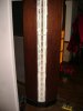
Here is a closer pic of the backside. As I mentioned, some of the "louvers" are missing, but it looks somewhat burnt too. Is this the way they normally look?

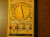
To test capacitance, should I be able to get a reading from this sort of panel as well? The meter I am using is a Knight 810. Seems like a nice meter (I picked it up at a garage sale), but the capacitance area seems to assume you are testing just a capacitor and stick one end of it into the tiny holes (under Cx), the other end on ground? Using a new cap, this was the only way I could get any sort of reading.

To test capacitance, should I be able to get a reading from this sort of panel as well? The meter I am using is a Knight 810. Seems like a nice meter (I picked it up at a garage sale), but the capacitance area seems to assume you are testing just a capacitor and stick one end of it into the tiny holes (under Cx), the other end on ground? Using a new cap, this was the only way I could get any sort of reading.