• The move to the new server is done. There are some software and database maintenance updates in process. This has us passing the hat around to help out. We appreciate any donations. Seriously, even a dollar helps. The payment page may be found here - https://www.audiokarma.org/support.html

Beveridge Model 5 - Restore

I'm not sure what the burned and crumbly looking stuff is, but if I understand the operating principle of the Beveridge, there should be absolutely no continuity (iow, infinite resistance) between the diaphragm and either stator; capacitance, yes, but I don't know how to measure it.

These are different than conventional esl's in that the normal way to do things is to bias the diaphragm to 3-5kV (which has extremely high surface resistance to prevent charge migration) and to supply the stators (through the audio step-up transformer/s) with a signal which has opposing charge on the front and back stators at any given instant, but which alternates in polarity and level depending on the AC audio input. This is the electrostatic force that moves the diaphragm.

The Beveridge is backwards in that the stators are held at constant charge while the low surface resistance aluminized mylar diaphragm alternates in voltage potential in accordance with the audio input.

I think that the aluminum frame should have continuity with the diaphragm. The "clear" parts of the epoxy were designed to insulate the darker "carbonized" sections (high resistance, constant charge) of the stators from the aluminum frames, so any foreign objects or damage allowing a current path between them would be a problem.
 
Selecting the appropriate range under F for Farads should allow you to measure capacitance with the regular test leads.
 
Selecting the appropriate range under F for Farads should allow you to measure capacitance with the regular test leads.

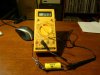
That's what I was assuming too, but using a small capacitor, I get no reading that way.
attachment.php


But when I connect one end in the Cx slots and the other to ground, I get a reading.
attachment.php
 

Attachments

  • P1040277.jpg
    P1040277.jpg
    86.5 KB · Views: 366
  • P1040279.jpg
    P1040279.jpg
    75.5 KB · Views: 368
I think you are supposed to select the appropriate range and insert the capacitor leads directly into the Cx sockets. None of the round test probe sockets are used.
 
One new meter and one new set of measurements! Seems my suspicion was correct, the meter I was using was faulty. I couldn't even get it to read resistance.

Using my new meter, I get a capacitance measurement of 1.94 nf frontside and 2.33 nf backside. Since we don't know what the range should be, I assume all we can say now is that at least we get some capacitance reading?
 
I'm going to give the panel a close inspection tomorrow to make sure there is nothing touching between the diaphragm and stators. If they check out, I'll need to focus on the crossover.

Can anyone give me some guidance on what I should check? I would think some of the caps probably need replacement by now.
 
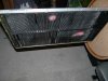
I've taken the panel out, given it as thorough a checking out as I can do. The gap between the stat and the diaphragm is VERY close, but I cannot see any place where they are touching. The broken segments look to me like they were broken during the manufacturing process as I can see no debris anywhere on the panel or inside the cabinet where there should be if broken while in operation or during a move.

I also get no continuity for both front/back of the panel as well. I put it back inside the cabinet since that is the safest place for it to ensure no little fingers or thrown toys can damage it. :D

Anyone know of anything else to check at this point on the panel?
 
One new meter and one new set of measurements! Seems my suspicion was correct, the meter I was using was faulty. I couldn't even get it to read resistance.

Using my new meter, I get a capacitance measurement of 1.94 nf frontside and 2.33 nf backside. Since we don't know what the range should be, I assume all we can say now is that at least we get some capacitance reading?

Hi,

I think that the difference in capacitance is caused, to some part, by the missing "louvres". Normally the capacitances should be about equal or balanced but your panel is missing some stator-area on one side, so there should be a difference.
Did you measure the other panel?
Did you get any capacitance reading on the other panel?


You can check the voltages on the PCB, but you will need a high voltage probe. Can you borrow one?
This should one be ok.
http://www.myflukestore.com/p1368/fluke_80k-6_kv_high_voltage_probe.php

Check the red and black wire coming out from the board close to the terminals. These are the +- high voltage to the stators. On my board it's about -1700 V and +1700 V if I remember correct.
It is modulated with audio signal - the stators are also "active"
Measure DC

The HV to the diaphragm is coming from the audio transformer and
there is no signal without input from your amp.

All high voltage (capacitors, resistors..) are on the on the PCB.
Also high voltage on the output from the big audio-transformer.(dangerous)
The other capacitors are for the crossover.

Regards
 
I just took the top off the other speaker.

Of note, the little sticker with the handwritten number is 34, the first speaker shown here with all the pics thus far is 33 (which is on the cabinet and the crossover).

So, for speaker 34, the measurements are:

Capacitance
Front: 2.13 nf
Back: 2.3 nf

For speaker 33 (pics), the measurements are:

Front: 1.94 nf
Back: 2.3 nf

I too was assuming the back would have been the lower value due to the broken "louvers", but now that I think about it, I noticed the handwritten "notes" on the side of the panel. I wonder if they broke them off to get it down to a certain range? The front also has a few broken off, but not as many as the back. I don't have room to lay 34 down, so I can't take the panel out at the moment.

attachment.php


I do not have a high voltage probe and am not sure if anyone local to me has one or not. So will need to think about next steps.
 

Attachments

  • P1040259.jpg
    P1040259.jpg
    97.2 KB · Views: 352
Last edited:
I've taken the panel out, given it as thorough a checking out as I can do. The gap between the stat and the diaphragm is VERY close, but I cannot see any place where they are touching. The broken segments look to me like they were broken during the manufacturing process as I can see no debris anywhere on the panel or inside the cabinet where there should be if broken while in operation or during a move.

I also get no continuity for both front/back of the panel as well. I put it back inside the cabinet since that is the safest place for it to ensure no little fingers or thrown toys can damage it. :D

Anyone know of anything else to check at this point on the panel?

Hi,

Is the frame surronding the panels made of steel or aluminium?
If it is alu there could be oxide on the wire connection point.
The wires going from the pcb up to the panel, are they ok?
You can measure the resistance of the wires.

I would also check the audio transformer, 1V input should give about 50 -100 V on the secondary side (the terminal connecting to the diaphragm) depending on the turns ratio.
You could dowload a free tone generator application for Pc or make a cd with some frequency tracks ,for example a 1 khz signal . Repeat that track on your cd.
Check the voltage on the speaker cables and adjust to 1 Volts.
Then measure secondary side of the transformer.
I have never done this myself but I think it should work.
 
This is no help with your current predicament, but I doubt a manufacturer would offer for sale a "broken" product like these with the damaged stators. I suspect, given what little I know about the Models 3 and 5, that you have an early set of 5's that suffered from panel failure and that someone tried to repair them by installing a set of Model 3 transducers which were somehow damaged in the exchange. AFAIK, they are electrically identical and interchangeable.

335, I think this idea of modulating the stator voltage as well as the diaphragm charge is pretty cool. I know that Beveridge did this with the original OTL powered speakers, but I didn't realize he did it with the passive ones, too. Kind of like a turbocharging effect, I guess?
 
This is no help with your current predicament, but I doubt a manufacturer would offer for sale a "broken" product like these with the damaged stators. I suspect, given what little I know about the Models 3 and 5, that you have an early set of 5's that suffered from panel failure and that someone tried to repair them by installing a set of Model 3 transducers which were somehow damaged in the exchange. AFAIK, they are electrically identical and interchangeable.

While I guess anything is possible, it would seem odd a Model 3 owner not having them fixed and sacrificing them for a Model 5. Plus, for it to fit snugly like it does, they would have had to completely modify the cabinet internals to accommodate the Model 3 stat and this looks too well finished for that to have happened. The regular Model 5 circuit board stat might be the same square inches, however, it is much thinner and would have been a loose fit in my Model 5 cabinet. For someone to go to so much trouble in a retrofit, I really can't see them being so sloppy and damaging the stat.

With the binding posts not matching up, I really think each speaker was a near custom set early on and unless we can find another early Model 5, we really won't be able to confirm.

At this point, although the capacitance is slightly off for one side, we don't know the panels will not work, correct?
 
Last edited:
Hi,

Is the frame surronding the panels made of steel or aluminium?
If it is alu there could be oxide on the wire connection point.
The wires going from the pcb up to the panel, are they ok?
You can measure the resistance of the wires.

I would also check the audio transformer, 1V input should give about 50 -100 V on the secondary side (the terminal connecting to the diaphragm) depending on the turns ratio.
You could dowload a free tone generator application for Pc or make a cd with some frequency tracks ,for example a 1 khz signal . Repeat that track on your cd.
Check the voltage on the speaker cables and adjust to 1 Volts.
Then measure secondary side of the transformer.
I have never done this myself but I think it should work.

Is the frame surronding the panels made of steel or aluminium? They are aluminum, so will look to clean those up.

The wires going from the pcb up to the panel, are they ok? Hmm, not sure how I will measure them since the meter wires are not that long. I guess I could connect them all together in series perhaps?

Audio transformer test: Will look to see about creating a tone CD. Will want to confirm with pics all of the test points before I go putting leads anywhere. :D
 
I just took the top off the other speaker.

Of note, the little sticker with the handwritten number is 34, the first speaker shown here with all the pics thus far is 33 (which is on the cabinet and the crossover).

So, for speaker 34, the measurements are:

Capacitance
Front: 2.13 nf
Back: 2.3 nf

For speaker 33 (pics), the measurements are:

Front: 1.94 nf
Back: 2.3 nf

I too was assuming the back would have been the lower value due to the broken "louvers", but now that I think about it, I noticed the handwritten "notes" on the side of the panel. I wonder if they broke them off to get it down to a certain range? The front also has a few broken off, but not as many as the back. I don't have room to lay 34 down, so I can't take the panel out at the moment.

attachment.php


I do not have a high voltage probe and am not sure if anyone local to me has one or not. So will need to think about next steps.

I made a voltage divider using two resistors before I found the probe on ebay.
The link below shows how to do. It will give 1/1000 of the total voltage if measuring over the 1 Mohm resistor. Mabye not precise but it will give you a hint wether the hv supply is workin or not.
I measured at the two stator connections, somewhere around 3 kV.

http://www.pocketmagic.net/?p=1569
 
While I guess anything is possible, it would seem odd a Model 3 owner not having them fixed and sacrificing them for a Model 5. Plus, for it to fit snugly like it does, they would have had to completely modify the cabinet internals to accommodate the Model 3 stat and this looks too well finished for that to have happened. The regular Model 5 circuit board stat might be the same square inches, however, it is much thinner and would have been a loose fit in my Model 5 cabinet. For someone to go to so much trouble in a retrofit, I really can't see them being so sloppy and damaging the stat.

With the binding posts not matching up, I really think each speaker was a near custom set early on and unless we can find another early Model 5, we really won't be able to confirm.

At this point, although the capacitance is slightly off for one side, we don't know the panels will not work, correct?

Considering the difference in thickness I agree.
My panels are only about 5 mm. Would be hard to get a thicker panel to fit - you can't open the speaker and there's just no room to work from the top.
 
.

The wires going from the pcb up to the panel, are they ok? Hmm, not sure how I will measure them since the meter wires are not that long. I guess I could connect them all together in series perhaps?

Yes, just connect them and check
 
335, I think this idea of modulating the stator voltage as well as the diaphragm charge is pretty cool. I know that Beveridge did this with the original OTL powered speakers, but I didn't realize he did it with the passive ones, too. Kind of like a turbocharging effect, I guess?

Yes, cool
Rick Beveridge wrote in another forum that's how all Bev's work
I guess it's the 5xR1 + C1 and 5xR2 + C2 in the schematic that's adding some audio signal to the stators, but I'm no expert. :)
 
Yes, cool
Rick Beveridge wrote in another forum that's how all Bev's work
I guess it's the 5xR1 + C1 and 5xR2 + C2 in the schematic that's adding some audio signal to the stators, but I'm no expert. :)

That's all hieroglyphics to me. :D

Current update, I have a high voltage probe on the way. In the meantime, will see about making that 1 Khz signal CD for testing. I use a Mac and have Garageband (although I have never used it), but I think it can be used to create a tone. I also have Audacity which should be able to do it, but again, I've never used it either, so will need to figure it out.
 
Back
Top Bottom