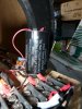
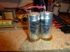
Hey no problem. Btw here's a cover I slapped together for that when I burned it.This has been bookmarked! Many, many thanks!!!


You are using an out of date browser. It may not display this or other websites correctly.
You should upgrade or use an alternative browser.
You should upgrade or use an alternative browser.
Beveridge Model 5 - Restore
- Thread starter Audio Fan
- Start date

Audio Fan
YT Channel - https://tinyurl.com/29zytwu9
Well, prepping to do some testing tomorrow and was just reviewing the wiring.
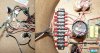
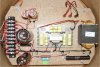
Below is a pic of the crossover and the binding post connections with numbers. Oddly enough, nothing is attached to two of the broken binding posts, so no idea why there are there. The front and back of the stat runs through the 6&9 and 5&8 wires. The woofer appears to be 3 & 4, however, the two twisted black and green wires going off to the left hookup to the woofer, so it seems the 7 and unmarked post would connect to it, but I can't understand how 7 is connected.

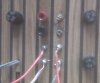
The external view of the binding posts for reference.

An overall pic of the crossover for reference.

So for testing, I should be fine to 5/8 ground and 6/9 positive to my test frequency and see if I can get some output.
Below is a pic of the crossover and the binding post connections with numbers. Oddly enough, nothing is attached to two of the broken binding posts, so no idea why there are there. The front and back of the stat runs through the 6&9 and 5&8 wires. The woofer appears to be 3 & 4, however, the two twisted black and green wires going off to the left hookup to the woofer, so it seems the 7 and unmarked post would connect to it, but I can't understand how 7 is connected.
The external view of the binding posts for reference.
An overall pic of the crossover for reference.
So for testing, I should be fine to 5/8 ground and 6/9 positive to my test frequency and see if I can get some output.
Attachments
Well, prepping to do some testing tomorrow and was just reviewing the wiring.
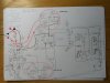
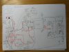
I made a couple pictures, both are for single amp - using internal crossover.
One is showing the woofer and the other the panel
I hope it will help you to identify which teminals to use.
Note, panel and woofer have separate fuses, the third fuse is for line voltage.
Attachments

Audio Fan
YT Channel - https://tinyurl.com/29zytwu9

It WORKS!!!!!!!!
After doing some initial testing as Ossi suggested, I found that the crossover was indeed creating good power. Ossi was kind enough to run the same tests on his and he got the same measurements. So why no sound? I kept thinking that somehow, they are just not getting the correct signal (or the stats were indeed dead) and that the stat needed a signal for the front/back together to work.
SOOOO, tonight I decided to just hook everything up and try it again, only this time, bi-wire it. First connections, just the woofer as before. Wasn't looking promising, so I thought, well, might as well try the other set. So I hooked them up and BING! Stats are singing!! But then no woofer, SOOOOO, again, connect the woofer, now everything plays just GREAT!!!!!!!!!!!!
I can't believe it.
Eurasian actually made that suggestion early on. I still needed to look at the internals to figure out what was where and we got a great dissection of the internals.
Now on to #34!!! :thmbsp:
Last edited:

Audio Fan
YT Channel - https://tinyurl.com/29zytwu9
Great news. Keep up the good work.
Yes indeed, keeping my fingers crossed #34 is in the same shape. Since the binding posts are a different configuration, will need to also review how they are wired.
On #33, no idea why they used four sets of posts when only three are in use, but oh well.
I need to order some replacement posts before I can put #33 back together.
Audio Fan
YT Channel - https://tinyurl.com/29zytwu9
Fantastic!
Indeed, I am still walking on air and still thinking this is a bit "too good to be true" until I get to test the other speaker.
I need to order some new binding posts, so will go ahead and replace them in this first speaker, but once I confirm the other speaker (#34) is working too, I want to replace the caps.
The primary caps are as follows:
Potter 3460J124M .12 MFD 2000 WVDC 43-8048
Potter 3260J254M .25 MFD 2000 WVDC 43-8019
I did a quick search and did not find these, but given these seem to require close tolerances I want to find an exact match, if possible. Does anyone know what kind of caps these are and can make a recommendation?
If these are the poly caps on the audio circuit board, I wouldn't bother replacing them as this type seldom goes bad or out of spec. The electrolytics and ceramics are the ones to worry about. If you are going to replace the electrolytics in the crossover section, I suggest that you try to find surplus oil filled ones rated for 50V or more. They are cheap and almost never fail. The downside is that they take up a lot of space and probably shouldn't be installed upside down--just in case one should leak.

HomerJSimpson
Addicted Member
Damn, how did these get by me....??
Very cool, I will have to listen to these bad boys....:yes:
Very cool, I will have to listen to these bad boys....:yes:
Audio Fan
YT Channel - https://tinyurl.com/29zytwu9
Damn, how did these get by me....??
Well, not all things speaker go through Homer's House of Speakers.

Very cool, I will have to listen to these bad boys....:yes:
Indeed! When I get them all gussied up and in place, we'll need to have a Central NC AK listening session.


. . . The primary caps are as follows:
Potter 3460J124M .12 MFD 2000 WVDC 43-8048
Potter 3260J254M .25 MFD 2000 WVDC 43-8019 . . . .
Sorry, late to the thread. These would be the power supply caps. Your bias supply will need the highest voltage rating of anything in the speaker. (I used to work on Infinity SS-1 systems)
The capacitance is for minor filtering. This just gets the bias voltage ripple out. But the voltage rating is important, the SS-1 rating was 8kV and was a cheap string of ceramic caps. I'm sure Beveridge chose better.
I'll follow more closely now.
Audio Fan
YT Channel - https://tinyurl.com/29zytwu9
Sorry, late to the thread. These would be the power supply caps. Your bias supply will need the highest voltage rating of anything in the speaker. (I used to work on Infinity SS-1 systems)
The capacitance is for minor filtering. This just gets the bias voltage ripple out. But the voltage rating is important, the SS-1 rating was 8kV and was a cheap string of ceramic caps. I'm sure Beveridge chose better.
I'll follow more closely now.
Hi Grainger!
Thanks for joining in on the thread.
I probably have everything backwards. I was assuming the Yellow (and one Blue) caps were the ones that would most need replacement, but I believe now having exchanged an email with 335* that the cans are probably the ones most in need of replacement (and one Blue).
Last edited:
A fresh start early here. Since there are high voltages there you might vacuum the electrostatics to remove any dust that would cause arcing as you apply voltage and volume. Since they are in essence parallel plate capacitors let them charge up for a week. Just plugging them in, testing, and unplugging they will never reach their maximum charge.
More later, less sooner.
More later, less sooner.
A fresh start early here. Since there are high voltages there you might vacuum the electrostatics to remove any dust that would cause arcing as you apply voltage and volume. Since they are in essence parallel plate capacitors let them charge up for a week. Just plugging them in, testing, and unplugging they will never reach their maximum charge.
More later, less sooner.
Good idea to vaccum the speakers, also remove the panels and carefully blow out dust from the lens with air pressure
The panels I have don't need that long charge time because there is no high resistane coating to be charged ,like in the old Quad's.
I guess removing power when not used could give a longer life and less dust collected in the panel.
Audio Fan
YT Channel - https://tinyurl.com/29zytwu9
I have some new binding posts on the way, but in the meantime, I wanted to start thinking about getting new caps. Here are close-ups of the other caps:


Anyone have any recent experience finding these sizes?
Anyone have any recent experience finding these sizes?