• The move to the new server is done. There are some software and database maintenance updates in process. This has us passing the hat around to help out. We appreciate any donations. Seriously, even a dollar helps. The payment page may be found here - https://www.audiokarma.org/support.html

Blown fuse and smokin’ resistor on Technics SA5170

Anonky

Kenwood KR-9600 / Pioneer SX-950 / Sony STR-GX10ES
Hello all. Have a technics SA5170 that blows fuse on power up according to its previous owner (the single fuse on the power supply and amp board). After inspection I identified a few potential problem caps and went ahead and empirically replaced them. Also noted a slightly discolored resistor (R635 on the power supply/amp board). I’ve already got an order in for several replacement resistors. But in the meantime since I replaced a few suspect caps, I figured perhaps those were possibly the etiology of the problem. I replaced the blown fuse (manual calls for 2A 125V) with a 2A 250V fuse and powered it on. Lights came on but I immediately saw smoke. Powered off unit and sure enough the smoke was coming from this suspect R635 resistor. Fuse didn’t blow but it was also only powered on all of 5 seconds.

so two questions:

1. is the fuse I replaced it with acceptable? Want to make sure I’m not risking blowing up the unit.

2. Where ought I look next to diagnose the etiology of this issue? Not the greatest with interpreting the schematics and exactly where to look next.

May finally be time for me to make a DBT…
 
Last edited:
Register to hide this ad
Hello all. Have a technics SA5170 that blows fuse on power up according to its previous owner (the single fuse on the power supply and amp board). After inspection I identified a few potential problem caps and went ahead and empirically replaced them. Also noted a slightly discolored resistor (R635 on the power supply/amp board). I’ve already got an order in for several replacement resistors. But in the meantime since I replaced a few suspect caps, I figured perhaps those were possibly the etiology of the problem. I replaced the blown fuse (manual calls for 2A 125V) with a 2A 250V fuse and powered it on. Lights came on but I immediately saw smoke. Powered off unit and sure enough the smoke was coming from this suspect R635 resistor.

so two questions:

1. is the fuse I replaced it with acceptable? Want to make sure I’m not risking blowing up the unit.

2. Where ought I look next to diagnose the etiology of this issue? Not the greatest with interpreting the schematics and exactly where to look next.

May finally be time for me to make a DBT…
Fuse you used is fine. Most likely blown drivers and/or outputs on that channel. Check TR609, 611, 613, 615 and associated resistors if found bad.

Definitely time to make a dim bulb tester.
 
Fuse you used is fine. Most likely blown drivers and/or outputs on that channel. Check TR609, 611, 613, 615 and associated resistors if found bad.

Definitely time to make a dim bulb tester.
When you say check these what exactly do you mean? Make my DBT first then power on and take some measurements about these components? Again, still new to this so explain like I’m 15 years old please lol
 
When you say check these what exactly do you mean? Make my DBT first then power on and take some measurements about these components? Again, still new to this so explain like I’m 15 years old please lol
The resistor is smoking because something is drawing excessive current through it, most likely a shorted transistor. Check them with a DMM in diode test mode, following this tutorial:
Bipolar Junction Transistor Testing Basics | Audiokarma Home Audio Stereo Discussion Forums
 
The resistor is smoking because something is drawing excessive current through it, most likely a shorted transistor. Check them with a DMM in diode test mode, following this tutorial:
Bipolar Junction Transistor Testing Basics | Audiokarma Home Audio Stereo Discussion Forums
Removed T609 from circuit and am not getting any reading across the base and emitter in diode test. I suppose that means it’s a dead short. Will proceed and test the other 3 you mentioned. Do the problems usually start with the transistor or is there likely a failure further upstream that caused transistor failure? Thanks
 
Removed T609 from circuit and am not getting any reading across the base and emitter in diode test. I suppose that means it’s a dead short. Will proceed and test the other 3 you mentioned. Do the problems usually start with the transistor or is there likely a failure further upstream that caused transistor failure? Thanks
Usually starts at the outputs and cascades back.

Check all 4 transistors and resistors R633,R631, R635, R639, R637, R639, R641, R643. Check Q607 while you're at it.
 
Usually starts at the outputs and cascades back.

Check all 4 transistors and resistors R633,R631, R635, R639, R637, R639, R641, R643. Check Q607 while you're at it.
Checking resistors for impedance (ohms) and the transistor using the diode instructions provided previously yeah?
 
Removed T609 from circuit and am not getting any reading across the base and emitter in diode test.


no reading meaning you meter shows what, precisely? If its 0.00 thats a short. If it shows the same thing connected as with the leads not connected to anything, thats an open.
 
Usually starts at the outputs and cascades back.

Check all 4 transistors and resistors R633,R631, R635, R639, R637, R639, R641, R643. Check Q607 while you're at it.
R633: 6 ohm

R631: can’t find this one and don’t see it in the manual

R635 (the fried one that has been replaced): 215 ohms

R639: 167 ohms

R637: 170 ohms

R639: 169 ohms

R641: 430 ohms

R643: 0.5 ohms

For what’s it’s worth I tested these in circuit. Going to pull the transistors out and test them next. Will update

edit: added r641 that was previously omitted
 
Last edited:
Y
no reading meaning you meter shows what, precisely? If its 0.00 thats a short. If it shows the same thing connected as with the leads not connected to anything, thats an open.
I stand corrected. I must’ve messed up somehow when I first checked this or the meter I used is awful. Used another (a bit more expensive meter I have) and got 800 (ohms?) on diode test with positive lead on the base and negative lead on emitter. What do these readings mean?

edit: just verified that my initial reading of tr609 was wrong. One of the plugs on my meter was loose. 800 ohms confirmed at tr609.
 
Last edited:
If you are testing them like a diode, you have to know what a diode does. It only lets current flow in one direction so if you have the positive meter lead on the base and the negative meter lead on the emitter and its showing a reading, reverse the meter leads and if it also shows a reading, it is shorted. If there is no reading when reversing the meter leads, then it is good.

If you happen to have any plain and simple diodes on hand, you will see how current flows in one direction but not in the other direction when reversing the meter leads.
 
R633: 6 ohm

R631: can’t find this one and don’t see it in the manual

R635 (the fried one that has been replaced): 215 ohms

R639: 167 ohms

R637: 170 ohms

R639: 169 ohms

R641: 430 ohms

R643: 0.5 ohms

For what’s it’s worth I tested these in circuit. Going to pull the transistors out and test them next. Will update

edit: added r641 that was previously omitted
Sorry, R631 was a typo, I should have typed R633.

Bad: R637
R641
Since R641 is bad, most likely Q613 is shorted.

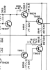
Here's a snippet of the schematic:
upload_2022-6-13_15-47-16.png
 
Anonky, also note that Rays posted schematic shows that the transistors are labeled as "TR" and not "Q".

"Q" is the universal notation for a transistor. "TR" in the above schematic also stands for TRansistor so they are both the same so technically TR613 is the same as Q613. Hope that clears up any confussion.
 
If you are testing them like a diode, you have to know what a diode does. It only lets current flow in one direction so if you have the positive meter lead on the base and the negative meter lead on the emitter and its showing a reading, reverse the meter leads and if it also shows a reading, it is shorted. If there is no reading when reversing the meter leads, then it is good.

If you happen to have any plain and simple diodes on hand, you will see how current flows in one direction but not in the other direction when reversing the meter leads.
Yeah I think I’m following this now. When I reverse the polarity the reading is “I” which is what it shows when nothing is connected.
 
Anonky, also note that Rays posted schematic shows that the transistors are labeled as "TR" and not "Q".

"Q" is the universal notation for a transistor. "TR" in the above schematic also stands for TRansistor so they are both the same so technically TR613 is the same as Q613. Hope that clears up any confussion.
Thanks Cademan. I don't want to confuse Anonky by using the wrong notation.

I looked right at the schematic, which clearly shows TR, not Q. I have the uncanny ability to look right at something and not see it. I often say I have tunnel vision with a blind spot in the middle. :(
 
Thanks Cademan. I don't want to confuse Anonky by using the wrong notation.

I looked right at the schematic, which clearly shows TR, not Q. I have the uncanny ability to look right at something and not see it. I often say I have tunnel vision with a blind spot in the middle. :(

You're fine. :D :thumbsup:
 
Y


I stand corrected. I must’ve messed up somehow when I first checked this or the meter I used is awful. Used another (a bit more expensive meter I have) and got 800 (ohms?) on diode test with positive lead on the base and negative lead on emitter. What do these readings mean?

edit: just verified that my initial reading of tr609 was wrong. One of the plugs on my meter was loose. 800 ohms confirmed at tr609.
A reading like that sounds like the meter was in ohm's mode, not diode test. Diodes usually show around .5 or .6 volts.
 

Attachments

  • 0569D6E1-3047-4F4A-90E4-9ADA7B34F4F7.jpeg
    0569D6E1-3047-4F4A-90E4-9ADA7B34F4F7.jpeg
    159 KB · Views: 36
Back
Top Bottom