• Please note that Audiokarma will be offline briefly for updates early on Monday morning, September 28th.

Blown fuse and smokin’ resistor on Technics SA5170

yeah, I'd cut the tabs off and mount the transistor. Can't quite tell but would the entire back of the transistor contact the heat sink if that tab was gone? If it does you're good to go. Just mount the transistor with a screw and a nut, or if it needs something to bridge the gap where that tab is, maybe use the cut-off bit of tab as a large "nut" to back it up.


but yeah if the transistor isn't mounted firmly to the heat sink, its going to incinerate. Having it nearby is nowhere near as useful as actually being in mechanical contact with the heat sink.
 
What are the originals and what did you use to replace them? Sadly those "bat wing" transistors are long out of production.
 
@Warren-Oates I believe I’m going to try to drill holes higher up the heat sink. Cutting the tabs off doesn’t seem feasible and would only leave half of the transistor in direct contact with the heat sink. Any idea what material the junk sink is made of? Gonna have to get drill bits to make a hole
 
@Warren-Oates I believe I’m going to try to drill holes higher up the heat sink. Cutting the tabs off doesn’t seem feasible and would only leave half of the transistor in direct contact with the heat sink. Any idea what material the junk sink is made of? Gonna have to get drill bits to make a hole

That really sounds like a very tough job to make it work. It should be Aluminum, easy to drill, but higher up sounds like the very very last resort.

What about the post directly above mentioning the Motorola Trans?

And did you check to see if the sink is symmetrical and could be rotated?
 
Looking at some pictures online, that sink kinda looks symmetrical. That back side looks like a nice surface for attachment. I cannot determine how it attaches to chassis by the pictures. Looking at it can you see how many screw hold it in place? Could it be removed and rotated 180? If so could new mounting holes be drilled to attached the sink to chassis, or an adapter bar used to secure it?

If that could be done you might have a perfect surface for mounting your transistors.
 
most heat sinks are extruded aluminum, basically metallic string cheese. Very easy to drill, just use a spritz of WD40 or other light oil to keep the chips from sticking to the drill bit.

if you can just flip the thing around and get a blank slate that would be a very nice solution indeed. Set it in there, mark your holes, then pull it to drill and tap.
 
Looking at some pictures online, that sink kinda looks symmetrical. That back side looks like a nice surface for attachment. I cannot determine how it attaches to chassis by the pictures. Looking at it can you see how many screw hold it in place? Could it be removed and rotated 180? If so could new mounting holes be drilled to attached the sink to chassis, or an adapter bar used to secure it?

If that could be done you might have a perfect surface for mounting your transistors.
The sink cannot be rotated (at least readily). My plan is to mount these transistors higher up on the heat sink and jump the legs down to the board with insulated wire. going to be ugly, I know, but I think at this point it’s the easiest solution. What size nut and bolt generally is used for this application (mounting to the heatsink)?
 
Well I wish you luck I hope it works out. I would not be brave enough to attempt what you are.

You will want a screw that freely moves through the hole in the trans but just barely, like no wiggle room. I nice pan head will help secure it. If there is any metal in the trans casing you will need to isolate the screw with a sleeve(and use mica or silpad). Don't torque the screws with any force, just firm snug. After you install I would ohm check every leg to ground, and each other leg. You want to be real sure there is no short before you power up even on dimbulb.
 
probably M3 or #6 I'd think, depending which language your hardware store speaks.

nylon screws are an option too, can't short through that, but they are very easy to over-tighten and strip so be careful if you do this.
 
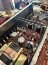
@Warren-Oates @gadget73 Happy July 4th! Behold this abomination. Hopefully don’t see fireworks later. Powers up well on DBT. Gonna run it for a little to see how it dissipates heat before I move to an unprotected power supply. Fingers crossed
 

Attachments

  • 4C61723A-F480-4A33-A482-5AA9105A3763.jpeg
    4C61723A-F480-4A33-A482-5AA9105A3763.jpeg
    148 KB · Views: 10
Hope it works. Those trans legs are a lot of bare metal. If you get it up and running you might want to add in some heat shrink tubing, reconnect things and then shrink your tubing to protect those long legs from shorting.
 
Hope it works. Those trans legs are a lot of bare metal. If you get it up and running you might want to add in some heat shrink tubing, reconnect things and then shrink your tubing to protect those long legs from shorting.
Last thing: I ought to check the bias as a last step here correct? And I should be able to do this with only a digital multimeter, yes?
 
yes, measure DC voltage across the emitter resistors, or whatever the manual specifies as test points. Sometimes its across both resistors at once, sometimes just one. Usually its some number of millivolts.
 
yes, measure DC voltage across the emitter resistors, or whatever the manual specifies as test points. Sometimes its across both resistors at once, sometimes just one. Usually its some number of millivolts.
I’ve measured dc offset at speaker terminals and it’s 6mV and -2mV respectively which seems fine. This is different though correct? And yes I’ll review the service manual tonight and check.
 
Back
Top Bottom