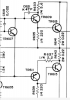
Try pressing the yellow button on the upper left while in diode/continuity mode.Tell me what I’m doing incorrectly please. Don’t ask how I took the picture….


Try pressing the yellow button on the upper left while in diode/continuity mode.Tell me what I’m doing incorrectly please. Don’t ask how I took the picture….

That just holds the reading. I actually whipped out the manual and that reading is in mV so 0.8V. Is that ok?Try pressing the yellow button on the upper left while in diode/continuity mode.
Maybe it is for that meter. All the ones I've used are in the neighborhood of .5-.6 volts.That just holds the reading. I actually whipped out the manual and that reading is in mV so 0.8V. Is that ok?
For what it’s worth I used another meter and got .73 V. Let’s assume it’s ok for now. I’m going to pull those other transistors you initially mentioned and test them too. So I’ll have checked TR609,611, 613 and 615. Will update shortly.Maybe it is for that meter. All the ones I've used are in the neighborhood of .5-.6 volts.
On my Fluke you use the yellow button to change from continuity mode to diode test mode. Couldn't see the label on the left hand button in the pic.

OK readings are below for the four transistors TR/Q609, 611, 613 and 614.. I’ve put each reading based on the diode measuring guidance. Positive lead was probed to the first letter (B-base, E-emitter, or C-collector) while the second letter was probed with the negative lead.Maybe it is for that meter. All the ones I've used are in the neighborhood of .5-.6 volts.
On my Fluke you use the yellow button to change from continuity mode to diode test mode. Couldn't see the label on the left hand button in the pic.
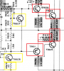
Correct. It's a good idea to print out the section of the schematic you're working on, and mark what you find wrong. This can help trace the path of destruction:OK readings are below for the four transistors TR/Q609, 611, 613 and 614.. I’ve put each reading based on the diode measuring guidance. Positive lead was probed to the first letter (B-base, E-emitter, or C-collector) while the second letter was probed with the negative lead.
TR609:
BE: 0.8v
BC: 0.8v
EB: - (no reading)
CB: -
CE: -
TR611 (this is PNP so I had to flip everything as I understand)
EB: -
CB: -
BE: -
BC: -
EC: 0.003v (continuity indicator was sounding?)
TR613:
BE: 0.23v
BC: 0.23v
EB: 0.23v
CB: 0.23v
CE: 000v (no volts but continuity indicator was sounding)
TR615:
BE: 0.18v
BC: 0.18v
EB: 0.7v
CB: 0.7v
CE: 000v (no volts but continuity indicator was sounding)
Based on the guidance in the post about measuring diodes/transistors, my untrained eye tells me TR611 is bad, and likely 613 and 615 as well. Is this correct? Thoughts? Next steps?

R633 5.8 ohm so about spot on. Are those transistors as far upstream as the problem likely goes? I can place an order for replacements whenever we are to that pointCorrect. It's a good idea to print out the section of the schematic you're working on, and mark what you find wrong. This can help trace the path of destruction:
View attachment 2592167
Check R633 too.
R633 5.8 ohm so about spot on. Are those transistors as far upstream as the problem likely goes? I can place an order for replacements whenever we are to that point
OK readings are below for the four transistors TR/Q609, 611, 613 and 614.. I’ve put each reading based on the diode measuring guidance. Positive lead was probed to the first letter (B-base, E-emitter, or C-collector) while the second letter was probed with the negative lead.
TR609:
BE: 0.8v
BC: 0.8v
EB: - (no reading)
CB: -
CE: -
TR611 (this is PNP so I had to flip everything as I understand)
EB: -
CB: -
BE: -
BC: -
EC: 0.003v (continuity indicator was sounding?)
TR613:
BE: 0.23v
BC: 0.23v
EB: 0.23v
CB: 0.23v
CE: 000v (no volts but continuity indicator was sounding)
TR615:
BE: 0.18v
BC: 0.18v
EB: 0.7v
CB: 0.7v
CE: 000v (no volts but continuity indicator was sounding)
Based on the guidance in the post about measuring diodes/transistors, my untrained eye tells me TR611 is bad, and likely 613 and 615 as well. Is this correct? Thoughts? Next steps?
Ok ok my secret is I had my old girl come and snap the pic lol somehow she hasn’t tossed me to the curb yet. Going to test those additional components after while here. Will update later tonight!Now I'm dying to know how the OP took the pic in post # 20...
TR607 is bad (getting continuity in both directions from collector to emitter and 000v), TR605 is good. To be safe, I also checked R629 and it was good as well.View attachment 2592384
Maybe. Check further back. For instance, TR611 was bad; check TR605, which is directly connected to TR611. And should TR605 test bad, test R629. TR607 is connected to both TR609 and TR611, and both of those are bad, so check it too.
The key here is to test until everything else in the area tests good. That will delineate the damaged area..
OK, that's probably the extent of the damage. The resistors before those components are high enough in resistance to limit current from damaging anything further back toward the front end of the amp.TR607 is bad (getting continuity in both directions from collector to emitter and 000v), TR605 is good. To be safe, I also checked R629 and it was good as well.
OK, that's probably the extent of the damage. The resistors before those components are high enough in resistance to limit current from damaging anything further back toward the front end of the amp.
After replacing these parts bring it up on the dim bulb first.

Gadget73 is spot on, and I should have mentioned this: whenever you have a bad output transistor you need to changed them all on that channel.2SD586 is the output transistor right? I'd suggest changing both it and it's companion with a complimentary set. Using two different transistors is probably going to behave poorly. Not sure what the preferred sub is these days, last few times I needed TO-3 transistors I used an MJE15003/MJE15004 pair.
So to be clear what all exactly should I replace?Gadget73 is spot on, and I should have mentioned this: whenever you have a bad output transistor you need to changed them all on that channel.