• The move to the new server is done. There are some software and database maintenance updates in process. This has us passing the hat around to help out. We appreciate any donations. Seriously, even a dollar helps. The payment page may be found here - https://www.audiokarma.org/support.html

Blown fuse and smokin’ resistor on Technics SA5170

------- On diode test I’m reading 1050 ohms in one direction and 800 in the other.

A diode test does not read ohms. Volts?

Weird that it was working for a while and then had a failure like that. That leads me to believe that the parts you replaced must have been installed correctly. Perhaps another issue that has been there the whole time, and is intermittent like a transistor going dolally once a certain temp is reached.

And to be clear your dimbulb signals short with the blown fuse replaced, but with the fuse removed it does not signal short? if you need to test for this fact you can do it with an even smaller bulb for a bit more safety.
 
looks like its being powered from a 27.5v line through a 1k resistor, so the max that could flow is 27.5 milliamps, or about 3/4 of a watt. Might be worth confirming that 27.5v line is in fact 27.5 volts. I also dont see that being enough current to make the DBT run at full brightness.
I’m good to run this with the short so long as it’s on the DBT right? Just wanna make sure that I can test it on DBT with the short so I can check that voltage.
 
------- On diode test I’m reading 1050 ohms in one direction and 800 in the other.

A diode test does not read ohms. Volts?

Weird that it was working for a while and then had a failure like that. That leads me to believe that the parts you replaced must have been installed correctly. Perhaps another issue that has been there the whole time, and is intermittent like a transistor going dolally once a certain temp is reached.

And to be clear your dimbulb signals short with the blown fuse replaced, but with the fuse removed it does not signal short? if you need to test for this fact you can do it with an even smaller bulb for a bit more safety.
Apologies — on my meter the diode test function is on the ohm section so I assumed that was the unit (incorrectly). Learning lots!

But yeah I’m inclined to think the same. I’m going to check this voltage mentioned when I get home tonight and hopefully get more info about what is going on.

DBT signals a short with the fuse replaced. I have not attempted to run the unit without a fuse. Is that advisable??
 
I would try a 40W bulb IF I did that. Whatever is shorting should also be getting hot, it will be a good time to detect heat or the smell of warm electronics as well as do your test. There is a risk involved in doing this, burnt traces etc.

You can for sure try to power it up without that fuse, if the short is gone your dimbulb will not glow so bright. And you will know for sure your problem lies within the circuitry that is controlled by that fuse.
 
I would try a 40W bulb IF I did that. Whatever is shorting should also be getting hot, it will be a good time to detect heat or the smell of warm electronics as well as do your test. There is a risk involved in doing this, burnt traces etc.

You can for sure try to power it up without that fuse, if the short is gone your dimbulb will not glow so bright. And you will know for sure your problem lies within the circuitry that is controlled by that fuse.
Hmmm I’m gonna probably just run with the power fuse on the 60w bulb I’m using for now. For what it is worth it is the main power fuse that blew. Of note there are speaker output fuses as well. Neither of those blew.
 
I would try a 40W bulb IF I did that. Whatever is shorting should also be getting hot, it will be a good time to detect heat or the smell of warm electronics as well as do your test. There is a risk involved in doing this, burnt traces etc.

You can for sure try to power it up without that fuse, if the short is gone your dimbulb will not glow so bright. And you will know for sure your problem lies within the circuitry that is controlled by that fuse.
Also I might add a heat sensing laser to my tool collection? Hmm decisions
 
I don't know how many fuses the 5170 has to protect it, it may have just one for circuitry, but you can still rule out anything before the fuse this way.

60W is half an amp or so, that's enough to burn stuff possibly. I was testing a pioneer SX680 a few days back, smoke on powerup with a 60W dimbulb. I switched to a 27W watt bulb had the bottom side exposed (this is where the smoke came from). Powered on with the 27W bulb, saw the solder pad smoke and spark form on it. I was able to find the short with minimal power and I didn't burn anything up. Just saying be as careful as you can.
 
I don't know how many fuses the 5170 has to protect it, it may have just one for circuitry, but you can still rule out anything before the fuse this way.

60W is half an amp or so, that's enough to burn stuff possibly. I was testing a pioneer SX680 a few days back, smoke on powerup with a 60W dimbulb. I switched to a 27W watt bulb had the bottom side exposed (this is where the smoke came from). Powered on with the 27W bulb, saw the solder pad smoke and spark form on it. I was able to find the short with minimal power and I didn't burn anything up. Just saying be as careful as you can.
I’m that case maybe I will get a lower watt bulb. Appreciate the advice truly
 
can't really check zeners very effectively on diode check. Need a power supply and a current limiting resistor. Measure across the diode.

or since its in circuit, just measure across it while it has power. Confirm the 27v supply has 27v, and measure volts across the diode. If its shorted it will read 0v across the diode and 27v across the 1k resistor it connects to. If its good it should read about 22 volts (assuming its a 22v diode, I can't read it super clearly) and about 5v across the 1k resistor.

either way I don't think a shorted zener is going to make the DBT run full brightness. It just can't flow enough current to cause that to happen with a 100w lamp.
 
can't really check zeners very effectively on diode check. Need a power supply and a current limiting resistor. Measure across the diode.

or since its in circuit, just measure across it while it has power. Confirm the 27v supply has 27v, and measure volts across the diode. If its shorted it will read 0v across the diode and 27v across the 1k resistor it connects to. If its good it should read about 22 volts (assuming its a 22v diode, I can't read it super clearly) and about 5v across the 1k resistor.

either way I don't think a shorted zener is going to make the DBT run full brightness. It just can't flow enough current to cause that to happen with a 100w lamp.
And @Warren-Oates so the short was one of the power transistors I replaced. Not sure why it shorted though. All I can imagine is it overheated? Regardless I replaced both in that channel and that zener just for good measure. Now the unit powers up on 60w DBT, no shorts indicated. Playing music fine on the DBT as well. I am noticing the channel I’ve had all my troubles with is running hotter than the other (using my new infrared temp gun) while on the DBT and that’s likely due to two thing: 1. It’s much more proximal to the lamps which are hot as well as a larger resistor which is getting up to 140F just on the DBT. 2. Due to the size of the replacement power transistors I wasn’t able to screw mount them on the heat sink. They’re just kind of on the board and the insulator micas are separating them from the heat sink.

before I proceed further is there anything obvious I need to check? I’m afraid I’m just going to short the power transistors again.
 
Screw them down, they will overheat unless you do. If you have to drill new holes, that's what you'll have to do. The heat sink compound is only intended to fill the surface texture of the heat sink and metal back on the transistors. A think coating is a pretty good thermal INSULATOR, the opposite of what you want.

Have you set the bias on the newly repaired channel?
 
You must still have fuse lamps in there, if I recall the are VERY easy to access on that line. You might consider switching to nice cool warm white LEDs. Technics are famous for very toasty power resistors, but 140 should not be a problem for it. HPMguy has some awesome advice there, exactly what you should do next to help cool that thing.

**Also make sure your micas are not ripped up. You can test for a short on your output trans before even powering up. That could be why it blew, shorted to the heat sink? Get new mica or a silpad if you need, but don't power up shorted.
 
Screw them down, they will overheat unless you do. If you have to drill new holes, that's what you'll have to do. The heat sink compound is only intended to fill the surface texture of the heat sink and metal back on the transistors. A think coating is a pretty good thermal INSULATOR, the opposite of what you want.

Have you set the bias on the newly repaired channel?
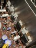
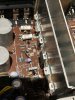
I’ll attach a photo below of the space I’m working with. The mounting brackets protrude out and are right in the way of where I would potentially mount them. Outside of somehow cutting those brackets, any ideas to mount them? Truly open to any ideas.

I have not set the bias yet. I was reading the schematic mentioning that and it was my next question. Can setting the bias be set using only a multimeter? The instructions in the schematic don’t seem super clear to me.
 
Last edited:
Screw them down, they will overheat unless you do. If you have to drill new holes, that's what you'll have to do. The heat sink compound is only intended to fill the surface texture of the heat sink and metal back on the transistors. A think coating is a pretty good thermal INSULATOR, the opposite of what you want.

Have you set the bias on the newly repaired channel?
Screw them down, they will overheat unless you do. If you have to drill new holes, that's what you'll have to do. The heat sink compound is only intended to fill the surface texture of the heat sink and metal back on the transistors. A think coating is a pretty good thermal INSULATOR, the opposite of what you want.

Have you set the bias on the newly repaired channel?
In the photo it’s the bottom two big transistors on the right
 

Attachments

  • 48E971DA-04A2-40DB-8D61-72AAED6BDFE7.jpeg
    48E971DA-04A2-40DB-8D61-72AAED6BDFE7.jpeg
    139.8 KB · Views: 20
  • 9E98D8F0-E963-4A25-9BC7-C6A67CAEAF9E.jpeg
    9E98D8F0-E963-4A25-9BC7-C6A67CAEAF9E.jpeg
    136.5 KB · Views: 20
Screw them down, they will overheat unless you do. If you have to drill new holes, that's what you'll have to do. The heat sink compound is only intended to fill the surface texture of the heat sink and metal back on the transistors. A think coating is a pretty good thermal INSULATOR, the opposite of what you want.

Have you set the bias on the newly repaired channel?
What are the odds that mounting a small aluminum or graphite free standing heat sink to the back of the transistor would suffice?
 
Won't work. Needs proper heatsink(the one already there). Hopefully somebody can post a pic of how to do it, or a similar one.
 
Won't work. Needs proper heatsink(the one already there). Hopefully somebody can post a pic of how to do it, or a similar one.
Only other idea I have which sounds like a headache and would look terrible is mount the transistor higher on the heat sink (above the slotted areas) and then run a wire from the transistor legs down to the board with only exposed wire right where it would go through the holes?
 
Others have suggested drilling some new holes to mount these transistors. Reading above I didn't see where you commented on that option, is there something that is preventing that tactic?
 
Others have suggested drilling some new holes to mount these transistors. Reading above I didn't see where you commented on that option, is there something that is preventing that tactic?
I posted a photo a few replies up. There are protruding mounting brackets for the original transistors that are in the way. To mount to the heat sink I would have to mount it higher up on the heat sink and run wire down to the PCB. That’s the only way I see it working. The transistors are just too large to make it fit under the mounting brackets.
 
I see that now. Here are the best options I can think of, a different transistor(I do not know what), take a dremel and cut off the tabs flush, bend the tabs straight up flush, see if by chance the sink could be flipped - is the back riser the same as the front but no holes. If you could flip it you may as well as replace all the trans with one style and drill appropriate holes.

At this point I'd trying a google on this issue, perhaps somebody has a good fix detailed elsewhere.
 
Back
Top Bottom