• The move to the new server is done. There are some software and database maintenance updates in process. This has us passing the hat around to help out. We appreciate any donations. Seriously, even a dollar helps. The payment page may be found here - https://www.audiokarma.org/support.html

Bogen AP-60 found in the dust

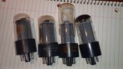
Not questionable, 3 of them look to be shot, that whiteness you're seeing on the tops indicate there is no vacuum left IE they've leaked

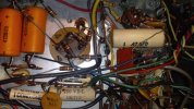
Here are a couple photos of the tubes close up and cleaned. They're all different makes. One has lost its vacuum. One has a deteriorated plastic base. Clearly these all need to be replaced, but I thought everyone would appreciate some close up photos.
 

Attachments

  • closeup of 7355  tubes (2).jpg
    closeup of 7355 tubes (2).jpg
    73.3 KB · Views: 44
  • closeup of 7355  tubes (4).jpg
    closeup of 7355 tubes (4).jpg
    69.9 KB · Views: 44
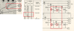
The concern is the black-yellow is 0.2 ohms and the schematic shows 2.9.
That looks like a SAMS error to me. Not uncommon.
On the primary side, things are less clear because the wire colors are very faded.
You can test for continuity anode-to-anode in each channel (pin 3 of the output tube sockets). Then check to be sure they're connected to the main B+ node. You can test the cathode windings by measuring from each cathode (pin 5) to ground.

Jack
 
yeah 2.9 ohms to that spot doesn't look right. It should be less than whatever the yellow lead measures. Less wire between that point and ground.

On mine with the open primary it read megohms instead of the 200-odd it should have read plate to plate.
 
You can test for continuity anode-to-anode in each channel (pin 3 of the output tube sockets). Then check to be sure they're connected to the main B+ node. You can test the cathode windings by measuring from each cathode (pin 5) to ground.

1. Each pair of pins 3 to 3 reads 250 ohms.

2. B+ to pins 3 on the 4 sockets read: 116, 130, 116, and 130 ohms. I used the downstream leg on R67 as the B+ test point. This should be the 410 volt line.

3. All pins 5 to ground read 7 ohms.
 
Possible they are side-getter tubes. I want to say my original set were that way and the replacements are top getter.

**edit** nevermind, I see the pics. 3 side, one top, and one that is "some assembly required". That one Bogen branded one looks like its got a warped plate and the base has been obviously toasty.
 
Last edited:
2.9 Ohms is an error - should be the lowest resistance value of all the secondaries - maybe 0.3 Ohms. Essentially zero Ohms unless you have an 4-wire ohmmeter. Sounds like transformers are OK. No problems with mixing brands of output tubes - 7355s were only made by GE, regardless of what name is on them. So finding matching ones may not be too hard, if they're NOS. Pricing has never gotten out of hand it's a low-demand tube, never used in guitar amps. (also $23 at findatube.com - my favorite tube source)

You might be able to disconnected the cans and replace with caps underneath, but it looks tight. Another option for the cap caps it to use clamp-mounted caps - they're about half the cost of replacement twist-locks - the clamps usually fit the same holes.
 
Last edited:
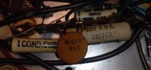
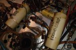
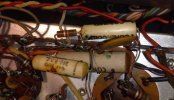
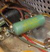
I need to line up the capacitors for this project. I will source the the large ones from Radio Daze. I can get the common ones from Digikey or Mouser, but I'm looking for confirmation on the correct types:

1. Numerous beige colored ones - plastic film capacitors? Are these polarized? (C34, C35, C36, etc)
2. A single green capacitor on the power supply circuit (C43, .047 uF, 600 volts)
3. Several orange cardboard and one large "Arcolytic"- plain electrolytic polarized? (C7, C8, C9, etc)
4. Numerous small orange/beige - tantalum capacitors? Should these be replaced? Or tested and only replaced if out of spec?
 

Attachments

  • 20240216_122439.jpg
    20240216_122439.jpg
    67.7 KB · Views: 15
  • 20240216_122446.jpg
    20240216_122446.jpg
    113 KB · Views: 15
  • 20240216_122453.jpg
    20240216_122453.jpg
    98.1 KB · Views: 17
  • 20240216_122529.jpg
    20240216_122529.jpg
    153.5 KB · Views: 17
  • 20240216_122551.jpg
    20240216_122551.jpg
    83.6 KB · Views: 17
The round beige discs are ceramic, unlikely to be bad. Not polarized, and should be fine to sub with film if needed.

The white tubular ones might be paper or mylar. Replace with film, polypropylene is a fine choice. They are not polarized.

Micamold Tropicaps are paper, sub with polypropylene. Unless it happens to be across the power line, then it should be a safety rated capacitor.

The Arcolytic is just an electrolytic. Same with the cardboard sleeved jobs. Common polar electrolytic will sub, less selection in axial but they fit better than radials in this case.
 
See schematic images below for capacitor C3. This is one of the large ones. I just need confirmation that because all 4 values for this capacitor are the same, it doesn't matter how it's soldered back in. In other words, every terminal should give the same value.

I won't have the same luxury for C1 and C2; the terminals on those are not the same so I have to make sure they're connected to the correct parts of the circuit.

I need to remove C3, see how it's attached, and if I need to order a new plastic plate or not. So while i'm in there, I need to make sure I know what was connected to what just in case. However it doesn't appear to matter for C3.
 

Attachments

  • C3 replacement.png
    C3 replacement.png
    359.9 KB · Views: 7
Sure looks that way. Four sections, 20uf at 350v each.

confirm whats actually written on the can just in case the schematic is wrong or some change was made.
 
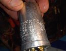
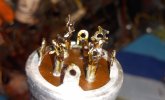
C1 is out. My first impression is that they didn't wire this thing together for ease of service. Every wire and resistor lead was wrapped around or through a terminal on C1. It took me 20 minutes working with flux paste, desoldering braid, Hakko soldering iron, needle nose pliers, and flush wire cutters. My goal was to ensure the phenolic/plastic plate on the top side would stay put, and it did since it's riveted on. So I don't need phenolic plates wih the new capacitors. I did check, yes, the values on the cap C1 do match the schematic: 20 uf / 550 volts for all 4 terminals. The aluminum case of C1 has 4 tabs which are what hold it to the case, as someone mentioned.

Thank you to everyone for your help on this project.
 

Attachments

  • C1 pre- removal20240220_163811 (2).jpg
    C1 pre- removal20240220_163811 (2).jpg
    116.8 KB · Views: 15
  • 20240220_170931.jpg
    20240220_170931.jpg
    94.1 KB · Views: 15
  • 20240220_170920.jpg
    20240220_170920.jpg
    71.8 KB · Views: 15
Last edited:
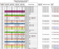
This project is still alive. I've been sidetracked with other projects but managed to work up a spreadsheet of the required electrolytic and poly capacitors with pricing and part numbers at Mouser. All of the capacitor are VIshay or Cornell-Dublier parts, except the ones from Hayseed Hamfest. The old green "Micamold Tropicap" is a one-off 600 volt capacitor that filters out high frequencies on the AC side of the power supply. It just shorts them to ground. I used a so-called 'safety cap' for that. I realzied that nearly everything that's not a ceramic capacitor appears in pairs, which I suppose is because this amplifier has 2 channels.
 

Attachments

  • Screen grab of capacitor spreadsheet 2.png
    Screen grab of capacitor spreadsheet 2.png
    373.2 KB · Views: 1
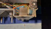
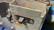
I took the AP-60 outside to the workbench to clean the switches and potentiometers. That freed them up considerably. One problem is the power switch that is really loose. I tested the continunity on it, and it's flakey. Can anyone reccomend a modern replacement for this switch? See the photos.

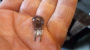
Also, there is a small bi-pin lamp which is the power on indicator. It has no numbers on it. Can anyone reccomend a replacment for this? Also in the pics.
 

Attachments

  • front panel power switch (1).jpg
    front panel power switch (1).jpg
    61.8 KB · Views: 13
  • front panel power switch (3).jpg
    front panel power switch (3).jpg
    62.6 KB · Views: 12
  • front panel power switch (4).jpg
    front panel power switch (4).jpg
    68.7 KB · Views: 13
  • lamp - bi pin (2).jpg
    lamp - bi pin (2).jpg
    60.5 KB · Views: 13
One problem is the power switch that is really loose. I tested the continunity on it, and it's flakey. Can anyone reccomend a modern replacement for this switch?
NOS slide switches like this frequently show up on eBay. Sometimes the sellers list dimensions like hole spacing, sometimes not. You might need to buy two or three different switches to find one that's reasonably identical, but I would do this rather than use a Chinese replacement. Be sure to equal or exceed the electrical ratings of the existing switch. This is often printed somewhere on the body of the switch itself.

Jack
 
Mouser sells new versions of the slide switch. I use them often on old amps that have 2 pole accessory receptacles. Same hole spacing and the opening is perfect. Brand is Apem. Check the mounting hole distance to be certain. The Apem switches are tapped for 4-40 machine screws. Your switch looks like it has a bit longer slider but you can check the Apem spec sheet and see if it will work for you.

 
Mouser sells new versions of the slide switch. I use them often on old amps that have 2 pole accessory receptacles. Same hole spacing and the opening is perfect. Brand is Apem. Check the mounting hole distance to be certain. The Apem switches are tapped for 4-40 machine screws. Your switch looks like it has a bit longer slider but you can check the Apem spec sheet and see if it will work for you.


Thanks for the rec. Fortunately it looks like these switches are not hard to come by. This one is similar but about a dollar more:


The 1.125" hole spacing and 1.38" front face width are identical to the original switch. However I like the threaded 4-40 machine screw holes on the Apem. That would make for a cleaner installation. I'm not oppsed to using a new old stock vintage replacement either if one turns up on Ebay.
 
Back
Top Bottom