

You are using an out of date browser. It may not display this or other websites correctly.
You should upgrade or use an alternative browser.
You should upgrade or use an alternative browser.
Bogen AP-60 found in the dust
- Thread starter GrandDesigns
- Start date
-
- Tags
- ap-60 bogen bogen ap-60 tube amp

GrandDesigns
New Member
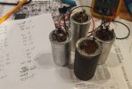
This receiver has 4 can caps. I installed the last one today so I measured the values of the old ones. Here are the results:
Required value - measured value (all values in uF)
C1:
20 - 40
20 - out of range
30 - 57
C2:
20 - 90
10 - 50
20 - 75
10 - 30
C3:
20 - 35
20 - 35
20 - 33
30 - 0.56
C4:
2000 - 0.47
As predicted these are all in bad shape.
By the way, the new can caps from Hayseed Hamfest are great looking and appear to be well made.
I've been hitting my local electronic parts store to get resistors because it's a fun place to visit, and I'm not paying Mouser $8 to ship me 78 cents of parts, even if they do get here fast.
Required value - measured value (all values in uF)
C1:
20 - 40
20 - out of range
30 - 57
C2:
20 - 90
10 - 50
20 - 75
10 - 30
C3:
20 - 35
20 - 35
20 - 33
30 - 0.56
C4:
2000 - 0.47
As predicted these are all in bad shape.
By the way, the new can caps from Hayseed Hamfest are great looking and appear to be well made.
I've been hitting my local electronic parts store to get resistors because it's a fun place to visit, and I'm not paying Mouser $8 to ship me 78 cents of parts, even if they do get here fast.
Attachments

Digikey ships for free if you mail the order with a check. No minimum order requirement. I do this frequently, even when the order is larger.I'm not paying Mouser $8 to ship me 78 cents of parts, even if they do get here fast.
Jack
GrandDesigns
New Member
I have not been able to find an instruction manual for this AP-60. Even after speaking to two people at Bogen, they claim not to have anything tihs old. I need help understanding how to configure the rear panel speaker impendence jumpers.
The schematic shows various resistances for these 4 terminals but that doesn't seem to directly relate to what speaker would be connected.
Searches for "impedance selector terminal board" don't turn up anything helpful.
I will be testing this unit with a pair of 6 ohm speakers.
The schematic shows various resistances for these 4 terminals but that doesn't seem to directly relate to what speaker would be connected.
Searches for "impedance selector terminal board" don't turn up anything helpful.
I will be testing this unit with a pair of 6 ohm speakers.
Attachments
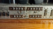
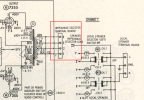

making the assumption that its the same as my DS-225, your output impedance options are 4, 8, 16, and 32 ohms going from 1-4. Pick whichever matches your speakers, guessing 4 or 8 so 1 or 2 respectively. Put the flying lead on that. Speaker leads will go to L, R and Gnd on the Local Speakers terminal
or if you want to bypass the switch, use Gnd and speaker positive goes to 1 or 2 on the upper terminal strip. Ignore the flying lead and all the rest of it.
or if you want to bypass the switch, use Gnd and speaker positive goes to 1 or 2 on the upper terminal strip. Ignore the flying lead and all the rest of it.

GrandDesigns
New Member
She's alive, but not happy. Clearly more work is needed. Here are the problems and symptoms I'm seeing:
1. It's outputting a fine static, almost like white noise, like you'd hear on an FM radio with no signal. The volume knob works to increase and decease the static, but there's a base level of noise even with the volume all the way down.
2. One of the two 12AX7 tubes lights up immediately at power on, and then dims down in 2 or 3 seconds. This problem follows the tube if I swap it to the other socket, but it doesn't light up as bright in the other socket. I may have a workable spare I can swap in but I'll have to check.
3. The static is on both channels, but only one channel of treble and base control has any effect. (this unit has independent L and R treble and bass controls). It might be too early for this to mean anything
4. I could not get an audio input signal to appear on the FM, tape, or aux inputs, although the RCA connectors do not offer firm physical connections so I need to test the contInuity on them, or wire something in directly.
5. The volume knob is still really noisy/scratchy so my cleaning job was not extensive enough.
The power indicator and speaker indicator lights all appear to work. Small step forward. I may have to admit failure and take the thing to the local repair guy who works on vacuum tube equipment However I am not opposed to troubleshooting the thing.
1. It's outputting a fine static, almost like white noise, like you'd hear on an FM radio with no signal. The volume knob works to increase and decease the static, but there's a base level of noise even with the volume all the way down.
2. One of the two 12AX7 tubes lights up immediately at power on, and then dims down in 2 or 3 seconds. This problem follows the tube if I swap it to the other socket, but it doesn't light up as bright in the other socket. I may have a workable spare I can swap in but I'll have to check.
3. The static is on both channels, but only one channel of treble and base control has any effect. (this unit has independent L and R treble and bass controls). It might be too early for this to mean anything
4. I could not get an audio input signal to appear on the FM, tape, or aux inputs, although the RCA connectors do not offer firm physical connections so I need to test the contInuity on them, or wire something in directly.
5. The volume knob is still really noisy/scratchy so my cleaning job was not extensive enough.
The power indicator and speaker indicator lights all appear to work. Small step forward. I may have to admit failure and take the thing to the local repair guy who works on vacuum tube equipment
However I am not opposed to troubleshooting the thing.
Any chance you can post the full PDF schematic?
Is it a European tube? Many of those are known to flash on power-up. Nothing wrong with it, just a thing they do.
without a schematic I don't know the full signal path here but since the volume control doesn't stop it, at least some of it must be coming from after the volume control. If there is a tube immediately downstream of that, try pulling it and see if that stops it.
Is it a European tube? Many of those are known to flash on power-up. Nothing wrong with it, just a thing they do.
without a schematic I don't know the full signal path here but since the volume control doesn't stop it, at least some of it must be coming from after the volume control. If there is a tube immediately downstream of that, try pulling it and see if that stops it.
GrandDesigns
New Member
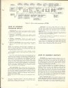
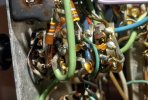
Schematic attached.
I made some progress:
1. I realized I had never cleaned the "balance adjust" potentiometers which are in the output transformer sections. So those are cleaner now.
2. I re-cleaned the 4 volume pots.
3. I checked continity from the AUX inputs to the output side of the source selector pots and that path is good.
4. I swapped the 12AX7 tube for a "strong" spare and that made no difference in sound, but it doesn't flash on startup.
5. I bypassed the normal speaker terminals as Gadget73 mentioned, in order to rule out flakey speaker select circuitry, however that did not make a difference.
Now what is happening:
1. The FM radio static comes and goes, and a 60 Hz hum comes and goes.
2 . I did get the thing to play channel #2 of audio with the volume knob at 100%. Anything less than 100% and I was getting static and popping. 3. After about 10 minutes of music from channel 2, the thing returned to humming and scratching and the volume knob even at 100%.
4. Audio from channel 2 is somehow making its way to channel 1 speaker.
So I think the volume pots are junk, and that could be the source of the missing channel 1 audio. Holy cow, replacing the 4 gang volume pots will be a chore. These are 100K pots.
I made some progress:
1. I realized I had never cleaned the "balance adjust" potentiometers which are in the output transformer sections. So those are cleaner now.
2. I re-cleaned the 4 volume pots.
3. I checked continity from the AUX inputs to the output side of the source selector pots and that path is good.
4. I swapped the 12AX7 tube for a "strong" spare and that made no difference in sound, but it doesn't flash on startup.
5. I bypassed the normal speaker terminals as Gadget73 mentioned, in order to rule out flakey speaker select circuitry, however that did not make a difference.
Now what is happening:
1. The FM radio static comes and goes, and a 60 Hz hum comes and goes.
2 . I did get the thing to play channel #2 of audio with the volume knob at 100%. Anything less than 100% and I was getting static and popping. 3. After about 10 minutes of music from channel 2, the thing returned to humming and scratching and the volume knob even at 100%.
4. Audio from channel 2 is somehow making its way to channel 1 speaker.
So I think the volume pots are junk, and that could be the source of the missing channel 1 audio. Holy cow, replacing the 4 gang volume pots will be a chore. These are 100K pots.
Attachments
GrandDesigns
New Member
If there is a tube immediately downstream of that, try pulling it and see if that stops it.
Great idea. I pulled the two 7247 tubes (V3 and V9). These are just after the volume pot and right before the power amp tubes. This cleared up all of the static and popping but I am still hearing a very low level hum on both channels equally. That may be the least of the problems right now.
low level hum might be the balance pots misadjusted. This doesn't have a direct way of adjusting it with a meter, but if you adjust them for minimum hum on each channel, its where it belongs. That will be equal current flow on each channel. Whether its the correct amount of current flow is a different question. May as well do that with the 7247 out since its otherwise quiet now.
Try grounding pin 2 on V3 and V9 with them installed and see if thats quiet.
also if you haven't, clean the pins and sockets for the small tubes. Inter-dental brushes dipped in whatever contact cleaner you like do a nice job on sockets, a magic eraser does well on pins. Just make sure its fully discharged before sticking anything into the sockets.
also clean the tape monitor switch. problems there will kill the signal getting through the amp.
Try grounding pin 2 on V3 and V9 with them installed and see if thats quiet.
also if you haven't, clean the pins and sockets for the small tubes. Inter-dental brushes dipped in whatever contact cleaner you like do a nice job on sockets, a magic eraser does well on pins. Just make sure its fully discharged before sticking anything into the sockets.
also clean the tape monitor switch. problems there will kill the signal getting through the amp.
GrandDesigns
New Member
low level hum might be the balance pots misadjusted...
Try grounding pin 2 on V3 and V9 with them installed and see if thats quiet.
..clean the pins and sockets for the small tubes.
..also clean the tape monitor switch.
Thanks for the suggestions. I will do all of these.
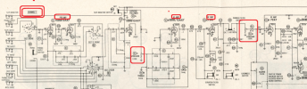
About replacing the volume pot: This looks to be an unusual part because of the coaxial, 4 gang design. I contacted Mark at oldradioparts.net to see if has a replacement. Mouser has a modern part from ALPS. The call the 4 gang varant the "quad". However it only has a single shaft, which I don't mind, and I'd have to see if would even work physically (shaft length, size). The only 4 gang variant is also motozied and I could not find this in a non-motorized version that also is 100K. I also don't know if the resistance taper would match what the original part has. Bourns also has a 4 gang 100K pot but it's short shafted.
I also find it interesting that the pot is 4 ganged because each channel uses two potentiometers in different areas for both channel 1 and 2 circuits. Surely there is a reason for this, but it's beyond me. It occurs to me that designing electrical circuits is like many other things: They get more complicated over time for various reasons. In the world of cars and electronics, I suppose the designers are adding features to entice the consumer, and that brings complexity.
The older I get, the more I want simplicity and reliability.
Attachments
GrandDesigns
New Member
The project is at a standstill. I made email initial contact with Mark Oppat at oldradioparts.net, but have not been able to make contact again. He replied that he had a replacement volume potentiometer and I should send photos, which I did, but have not heard back. I called today and left a message. So I need to come up with a plan to keep the project moving forward. I'd like to deal with the flakey volume knob pot:
1. Does anyone have any other potential source for a 4 gang, coaxial, 100K ohm potentiometer? This is an unusual part and I can't find a modern replacement, short of Alps part # RK16814MGA0K which is a $25 part with a motorized control and PCM mounting design.
2. What are my options to either bypass the pot, or put in a fixed resistor as either a temporary or permanant measure? I can control volume externally, even as a temporary measure.
3. Do I assume the taper of the original part is an 'audio' paper?
4. Any other ideas on a workaround? For example I could use two 2-gang 100K pots, but I'd have to mount them somewhere, such as putting the second one in the location for the original "blend" control which I do not need. That clearly moves away from the original design of this unit which is not ideal.
Thanks!
1. Does anyone have any other potential source for a 4 gang, coaxial, 100K ohm potentiometer? This is an unusual part and I can't find a modern replacement, short of Alps part # RK16814MGA0K which is a $25 part with a motorized control and PCM mounting design.
2. What are my options to either bypass the pot, or put in a fixed resistor as either a temporary or permanant measure? I can control volume externally, even as a temporary measure.
3. Do I assume the taper of the original part is an 'audio' paper?
4. Any other ideas on a workaround? For example I could use two 2-gang 100K pots, but I'd have to mount them somewhere, such as putting the second one in the location for the original "blend" control which I do not need. That clearly moves away from the original design of this unit which is not ideal.
Thanks!
This amplifier appears to have a structure capable of creating an over-abundance of gain. That might be the reason two volume pots are required in each channel. The first insures the incoming signal won't overload the line stage, and the second controls signal levels (and the noise floor) entering the power amp. If it was mine, I would consider replacing the first pot with a fixed divider in each channel, something like 2:1 or 3:1, whatever is needed to eliminate the possibility of overloading V2/V3 and V8/V9 with standard signal levels. Then I would replace the physical 4-gang pot with a 2-gang log (audio) taper pot, which should be easy to find. That would control the levels into V3B and V9B, just as two sections do now. In a way, you're lucky it's designed the way it is. Nearly all integrated amps from that era use a special volume control with a tap for the loudness contour switch. This one allows replacing the volume controls with standard three-terminal pots without losing compensation functionality.
Jack
Jack
There are a few things that did volume like this, but not many. Its cutting signal into the preamp as well as out of the preamp. Makes for better signal to noise that way, instead of having low signal in with all of the gain and noise of the preamp on the output it cuts the output too.
but yeah if it doesn't actually need all that much gain, a simple fixed divider at the front and a volume control at the tail end of the preamp section would certainly get it done. Play with the divider values to make it perform sensibly. Probably going to have the phono stage as your limiting factor. They generally will have less output than any of the line-level sources so you may have to figure out a divider that lets you get good volume from that and just deal with the rest of it. Just make sure the total resistance on the fixed divider adds up to whatever that section of the volume pot did.
but yeah if it doesn't actually need all that much gain, a simple fixed divider at the front and a volume control at the tail end of the preamp section would certainly get it done. Play with the divider values to make it perform sensibly. Probably going to have the phono stage as your limiting factor. They generally will have less output than any of the line-level sources so you may have to figure out a divider that lets you get good volume from that and just deal with the rest of it. Just make sure the total resistance on the fixed divider adds up to whatever that section of the volume pot did.
GrandDesigns
New Member
Quick update: I did talk on the phone briefly to Mark Oppat at oldradioparts.net and he said he was hundreds of emails behind, and for reasons unknown to him he's getting swamped with requsts lately. He said to re-send my photos which I did, but no reply. I don't have any ill will toward the man because he must be very busy.
Anyhow, thanks for the advice on a workaround for this using a voltage divider. That does make sense, however the skills needed to engineer even that simple design are outside of my capability and would require I lean more on this community than I'd like to. I ordered a new pot that I believe should work, however the shaft is probably 5 or 10mm too short and it's not offered in a combination of features that includes a longer shaft. This is a 4 gang, 100K, single shaft pot with an audio taper. The contacts are PCB mount which isn't ideal, and I am not sure the D-shaft is exactly the same size. The shaft will also be too short. I may have to have my son 3D print an adapter that would 1) make the shaft longer, and 2) fit the original knob at one end and the new shaft at the other end.
So my next task is to thoroughly document the failing pot and what wires go where, then remove it from the chassis and prep the wires to be soldered to the new pot.
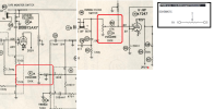
The replacement pot has 3 terminals for each gang: One is variable resistance (terminal 2) and the other two at each end (terminals 1 and 3). My question fou you is: Is there a specific order to terminals 1 and 3? Or should they functionally work identically? The schematic from the manufacturer doesn't seem to indicate there is any difference between terminals 1 and 3.
Anyhow, thanks for the advice on a workaround for this using a voltage divider. That does make sense, however the skills needed to engineer even that simple design are outside of my capability and would require I lean more on this community than I'd like to. I ordered a new pot that I believe should work, however the shaft is probably 5 or 10mm too short and it's not offered in a combination of features that includes a longer shaft. This is a 4 gang, 100K, single shaft pot with an audio taper. The contacts are PCB mount which isn't ideal, and I am not sure the D-shaft is exactly the same size. The shaft will also be too short. I may have to have my son 3D print an adapter that would 1) make the shaft longer, and 2) fit the original knob at one end and the new shaft at the other end.
So my next task is to thoroughly document the failing pot and what wires go where, then remove it from the chassis and prep the wires to be soldered to the new pot.
The replacement pot has 3 terminals for each gang: One is variable resistance (terminal 2) and the other two at each end (terminals 1 and 3). My question fou you is: Is there a specific order to terminals 1 and 3? Or should they functionally work identically? The schematic from the manufacturer doesn't seem to indicate there is any difference between terminals 1 and 3.
Attachments

Those would be 12AX7/ECC83 not 12V7 and there should be 6 of them not 3
Amplifier AP-60 Ampl/Mixer Bogen -Presto, David Co., Inc.; New York |Radiomuseum.org
Amplifier AP-60 Ampl/Mixer Bogen -Presto, David Co., Inc.; New York, NY /, build 1963 ?, 1 pictures, 1 schematics, 12 tubes, United States of Americawww.radiomuseum.org
If you have access to a tube tester by all means test all of those 12AX7's, as @Gadget mentioned they do stand a high chance of being good and usable and I'd wager that if so their audio fidelity would be equal if not better then new tubes.
This would save you a good amount of money as opposed to buying either NOS or new 12AX7's if you were to fully restore the amp if not then the worst case scenario is you would have 6 desirable pre amp tubes for the future.
Not questionable, 3 of them look to be shot, that whiteness you're seeing on the tops indicate there is no vacuum left IE they've leaked
View attachment 3119718
FWIW, those outputs are NOT necessarily shot - most 7355's have clear tops (gettering on the side)
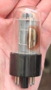

They will work opposite referenced to the center or wiper contact. Put your ohm meter on the wiper or center and then to one of the ends. Rotate the pot and see if the value increases or decreases depending on the rotation direction. One end needs to be the input and the other end is common/ground. For a volume control you want the wiper resistance to increase as you turn clockwise. It will only do this relative to one end or the other.My question fou you is: Is there a specific order to terminals 1 and 3? Or should they functionally work identically?