

You are using an out of date browser. It may not display this or other websites correctly.
You should upgrade or use an alternative browser.
You should upgrade or use an alternative browser.

Retrovert
Addicted Member
Aha! Problem solved!
Your crossover uses incorrect capacitor values for the inductors, which is why you prefer the "original" configuration. A hole at the low end and a hole at the upper end ruins the sound.
If you want to retain the original crossover points, replace the capacitors with values appropriate for 200 Hz and 1,500 Hz. That will, as per my previous explanation, remediate the mistake.
Or, if you want to use the crossover points used with the B-209, replace the inductors with the appropriate values.
Regardless of which option, components must change to have an even frequency response for the speaker.
So no need to purchase an additional set of crossovers, just undo the mistake made in refurbishing this one.
Your crossover uses incorrect capacitor values for the inductors, which is why you prefer the "original" configuration. A hole at the low end and a hole at the upper end ruins the sound.
If you want to retain the original crossover points, replace the capacitors with values appropriate for 200 Hz and 1,500 Hz. That will, as per my previous explanation, remediate the mistake.
Or, if you want to use the crossover points used with the B-209, replace the inductors with the appropriate values.
Regardless of which option, components must change to have an even frequency response for the speaker.
So no need to purchase an additional set of crossovers, just undo the mistake made in refurbishing this one.
Last edited:
Retrovert
Addicted Member
I point out applicable rules of Bozak Cult:
Rule 3 of Bozak Cult: Rebuild failure is never an option; no Bozak left behind.
Rule 4 of Bozak Cult: Don't panic; unless the speaker caught fire, melted into slag, or exploded, all rebuilds will ultimately succeed. This does not mean that all sizes of Bozaks will deliver optimal sound in all sizes of rooms.
Rule 3 of Bozak Cult: Rebuild failure is never an option; no Bozak left behind.
Rule 4 of Bozak Cult: Don't panic; unless the speaker caught fire, melted into slag, or exploded, all rebuilds will ultimately succeed. This does not mean that all sizes of Bozaks will deliver optimal sound in all sizes of rooms.

fjdds
Active Member
Out of sheer frustration, I took apart one of the crossovers, and re-assembled using the original (and probably wildly out of spec) components, following the N-105 schematic, not bothering to use the can. (My first attempt at this. My soldering skills need work.)
I put the receiver on mono, and did A/B comparisons.
Wow! The original 'presence' was back. The velvety mid just jumped out. I know a lot of this is personal preference, but I like it so much better. (I did notice that the volume was lower with the old components, so in order to do a meaningful A/B, I adjusted the volume when I switched sides so they were comparable.) The best way to describe the updated side is hollow, thin. That's gone when I went back to the original.
Sure, the highs are a bit harsh, but a new L-pad, replacing the faulty brightness control should do nicely.
Interestingly, the mid was 3-15 mfd capacitors in parallel with a 25 ohm resistor, and the high pass was a 5mfd capacitor in parallel with an identical 25 ohm resistor, slightly different than the values on the schematic. (50mfd mid, 8mfd tweeter).
Small difference, but nevertheless, perhaps Rudy knew what he was doing.
My next step is to order replacement components using the above values, and perhaps a supertweeter leg.
Tremendous help from all of you, especially Retrovert. Certainly, venturing into the Bozak world is a learning experience, albeit confusing.
I'm sure it's here somewhere, but I'm trying to locate a schematic, or diagram of the changes to the N-105 (non-tobinized) to accomodate a supertweeter. (and a band pass for the 200-y's, or could I just use a cap on the super-tweeter to pick up where the 200y's drop off)
Basic for you guys, but I'm learning as I go.
Thanks again.
I put the receiver on mono, and did A/B comparisons.
Wow! The original 'presence' was back. The velvety mid just jumped out. I know a lot of this is personal preference, but I like it so much better. (I did notice that the volume was lower with the old components, so in order to do a meaningful A/B, I adjusted the volume when I switched sides so they were comparable.) The best way to describe the updated side is hollow, thin. That's gone when I went back to the original.
Sure, the highs are a bit harsh, but a new L-pad, replacing the faulty brightness control should do nicely.
Interestingly, the mid was 3-15 mfd capacitors in parallel with a 25 ohm resistor, and the high pass was a 5mfd capacitor in parallel with an identical 25 ohm resistor, slightly different than the values on the schematic. (50mfd mid, 8mfd tweeter).
Small difference, but nevertheless, perhaps Rudy knew what he was doing.
My next step is to order replacement components using the above values, and perhaps a supertweeter leg.
Tremendous help from all of you, especially Retrovert. Certainly, venturing into the Bozak world is a learning experience, albeit confusing.
I'm sure it's here somewhere, but I'm trying to locate a schematic, or diagram of the changes to the N-105 (non-tobinized) to accomodate a supertweeter. (and a band pass for the 200-y's, or could I just use a cap on the super-tweeter to pick up where the 200y's drop off)
Basic for you guys, but I'm learning as I go.
Thanks again.
Retrovert
Addicted Member
Sonic Gap Remediation
Makes sense. You now hear a contiguous range of sound instead of one with gaps smack dab in the middle of where humans decently hear. Your rebuilder totally botched that job. I suggest obtaining a refund.
Ok. So that problem is now solved. I am, BTW, now filled with "I told you so". I knew something had to be wrong.
The ancient original capacitors are degraded, high ESR, leaky, etc. Ruining your sound, but not as ruined as with holes in the spectrum. Purchase some polypropylene Dayton capacitors from Parts Express as those are perfectly fine. I suggest constructing the large capacitors from smaller values parallel wired — something along the lines of 15 µF, two 10 µF, 5 µF, two 2µF, 1 µF — and bypassing (0.1 µF and 0.01 µF at a minimum) as I have elsewhere described in gory detail.
Capacitor Values
The 50 µF to 45 µF and 8 µF to 5 µF schange were likely not showing a design change to implement superior sonics, the changes likely were made to simplify stocking for parts. Eh, it's Bozak. It does these things.
The woofer's low-pass is:
This is not a critical value, as either value is likely close enough, particularly given 10% component tolerance. But as long as you are rebuilding, an opportunity exists to fix the cost-savings.
I'd stick with the 8 µF for the tweeters.
Super-Tweeter Modification
No super-tweeter modification schematic exists for changes to the N-105 since you're the first to build it. Other builds are for the N-10102 style crossover used in the B-209 three-ways, such as the B-302, B-313, B-502, etc.
Not to worry! A diagram customized for the N-105 is unnecessary!
Remember, the existing B-200Y is being modified to only run to 8k Hz. Whatever the low-end crossover point was — either 1,500 Hz for a B-800 system or 2,500 Hz for a B-205 system — does not change for the super-tweeter.
The sole difference is:
The existing low-pass capacitor, whatever its value, is retained. So the modification for the B-302 (three-way) is going to be identical in terms of the new driver (super-tweeter) and addition of an inductor to the old tweeter.
This requires two filters and two attenuators.
Two band-pass filters are needed:
The reason for cutting the second tweeter at 25,000 Hz is a protective measure to avoid destruction from high-frequency oscillation which is a common problem in many amplifiers. Tubes and transistors have great bandwidth, so any ultrasonic (high-frequency) signals may be amplified and put more energy into the tweeters than may safely be handled. The non-linearity at the high-end introduced by such a filter is inaudible. This is an arbitrary point chosen so that the first-order rolloff will not significantly impact the 20,000 Hz upper limit. One could likely use 20,000 Hz, and the damage to the high end would be undetectable by most listeners, even those with perfect hearing.
The band-pass filters are:
Two L-pad attenuators are needed, one for the original pair of tweeters, and one for the super-tweeter.
That clear?
Parts list:
Purchase air-core inductors and polypropylene capacitors. The parallel capacitor bank will be close enough given the tolerance of the parts.
Steve Smiley (@Steve Smiley) has successfully implemented the super-tweeter modification as have a few others. Looping him in to see if he has any additional input.
Makes sense. You now hear a contiguous range of sound instead of one with gaps smack dab in the middle of where humans decently hear. Your rebuilder totally botched that job. I suggest obtaining a refund.
Ok. So that problem is now solved. I am, BTW, now filled with "I told you so". I knew something had to be wrong.
The ancient original capacitors are degraded, high ESR, leaky, etc. Ruining your sound, but not as ruined as with holes in the spectrum. Purchase some polypropylene Dayton capacitors from Parts Express as those are perfectly fine. I suggest constructing the large capacitors from smaller values parallel wired — something along the lines of 15 µF, two 10 µF, 5 µF, two 2µF, 1 µF — and bypassing (0.1 µF and 0.01 µF at a minimum) as I have elsewhere described in gory detail.
Capacitor Values
The 50 µF to 45 µF and 8 µF to 5 µF schange were likely not showing a design change to implement superior sonics, the changes likely were made to simplify stocking for parts. Eh, it's Bozak. It does these things.
The woofer's low-pass is:
3.15 mH @ 8 Ω = 404 Hz ≈ 400 Hz
which matches the midrange crossover point provided by either capacitor value, paper specifications or what was on the board:45 µF @ 8 Ω = 442 Hz ≈ 450 Hz
50 µF @ 8 Ω = 398 Hz ≈ 400 Hz
50 µF @ 8 Ω = 398 Hz ≈ 400 Hz
This is not a critical value, as either value is likely close enough, particularly given 10% component tolerance. But as long as you are rebuilding, an opportunity exists to fix the cost-savings.
I'd stick with the 8 µF for the tweeters.
Super-Tweeter Modification
No super-tweeter modification schematic exists for changes to the N-105 since you're the first to build it. Other builds are for the N-10102 style crossover used in the B-209 three-ways, such as the B-302, B-313, B-502, etc.
Not to worry! A diagram customized for the N-105 is unnecessary!
Remember, the existing B-200Y is being modified to only run to 8k Hz. Whatever the low-end crossover point was — either 1,500 Hz for a B-800 system or 2,500 Hz for a B-205 system — does not change for the super-tweeter.
The sole difference is:
(1) Adding an inductor (low-pass) to the tweeter to create a band-pass built with whatever capacitor is in use
(2) Creating a band-pass — capacitor (high-pass) and inductor (low-pass) for the super-tweeter to create a band-pass
(3) Adding an L-pad to the B-200Y, to permit balancing
(4) Adding an L-pad to the super-tweeter, to permit balancing
(2) Creating a band-pass — capacitor (high-pass) and inductor (low-pass) for the super-tweeter to create a band-pass
(3) Adding an L-pad to the B-200Y, to permit balancing
(4) Adding an L-pad to the super-tweeter, to permit balancing
The existing low-pass capacitor, whatever its value, is retained. So the modification for the B-302 (three-way) is going to be identical in terms of the new driver (super-tweeter) and addition of an inductor to the old tweeter.
This requires two filters and two attenuators.
Two band-pass filters are needed:
(1) Existing tweeter, to run from 2,500 Hz to 8,000 Hz
(2) Supertweeter, to runs from 8,000 Hz to 25,000 Hz
(2) Supertweeter, to runs from 8,000 Hz to 25,000 Hz
The reason for cutting the second tweeter at 25,000 Hz is a protective measure to avoid destruction from high-frequency oscillation which is a common problem in many amplifiers. Tubes and transistors have great bandwidth, so any ultrasonic (high-frequency) signals may be amplified and put more energy into the tweeters than may safely be handled. The non-linearity at the high-end introduced by such a filter is inaudible. This is an arbitrary point chosen so that the first-order rolloff will not significantly impact the 20,000 Hz upper limit. One could likely use 20,000 Hz, and the damage to the high end would be undetectable by most listeners, even those with perfect hearing.
The band-pass filters are:
(1) Existing B-200Y, using the existing 8.2 µF capacitor (or whatever value is present) and add a 0.159 mH inductor to filter (2,500 Hz to 8,000 Hz)
(2) For the supertweeter use a 2.5 µF capacitor (technically 2.49 µF) and a 0.05 mH inductor to filter (8,000 Hz to 25,000 Hz)
(2) For the supertweeter use a 2.5 µF capacitor (technically 2.49 µF) and a 0.05 mH inductor to filter (8,000 Hz to 25,000 Hz)
Two L-pad attenuators are needed, one for the original pair of tweeters, and one for the super-tweeter.
That clear?
Parts list:
(Qty 1) 0.159 mH inductor
(Qty 1) 2.5 µF capacitor (again, ≈ 2.49 µF), constructed using something like (2) 1 µF + (1) 0.33 µF + (1) 0.1 µF + (1) 0.01 µF
(Qty 1) 0.05 mH inductor
(Qty 2) 8 Ω L-pads
(Qty 1) 2.5 µF capacitor (again, ≈ 2.49 µF), constructed using something like (2) 1 µF + (1) 0.33 µF + (1) 0.1 µF + (1) 0.01 µF
(Qty 1) 0.05 mH inductor
(Qty 2) 8 Ω L-pads
Purchase air-core inductors and polypropylene capacitors. The parallel capacitor bank will be close enough given the tolerance of the parts.
Steve Smiley (@Steve Smiley) has successfully implemented the super-tweeter modification as have a few others. Looping him in to see if he has any additional input.

rider33
Active Member
never underestimate the ability of seemingly small changes in cross-overs to produce out-sized changes in speaker performance. When I first got into this low those many years ago, I tended to focus on drivers & boxes and there is no denying that they can have a significant impact on what you hear. What is less obvious tho is that what is fed to them and how they blend can make an otherwise good system sound highly compromised. That is I think what drives a lot of classic speaker sales, systems that sound tired because the wiry bits have drifted out of spec. On the plus side, it is a whole lot easier & cheaper to play with caps & such than it is to switch drivers or modify box design. 'Have at it in the certain knowledge that once properly sorted, that system is capable of some lovely things.
Retrovert
Addicted Member
What does it mean to bypass with .1 and .01. Where do I place these additional caps?
In parallel. Capacitors in parallel together sum. The bypass adds a means for high-frequency signal to rapidly shuttle in/out of the capacitor, because charge distribution across smaller plates more rapidly occurs. Larger capacitors take longer to store charge, which causes non-linear behavior with frequency, aka distortion.
This is why I suggest building larger capacitors from smaller ones. The difference in cost, essentially packaging, is negligible because automation had greatly reduced the prices of components.
fjdds
Active Member
Ordered parts for the re-cap of the N105 to as close to original specs as I can get. In the meantime, I returned the other side to the original configuration with the old parts, and I prefer it so much more. Can't wait to hear it with fresh components.
Any thoughts on replacing some of the 200y tweeters with something that extends higher, instead of adding a super-tweeter. Would this work? I read somewhere on AK that someone was using an SEAS tweeter instead of the 200y.
Thanks.
Any thoughts on replacing some of the 200y tweeters with something that extends higher, instead of adding a super-tweeter. Would this work? I read somewhere on AK that someone was using an SEAS tweeter instead of the 200y.
Thanks.
Retrovert
Addicted Member
I suggest being wary of ancient capacitors from the 1960s. If a capacitor shorts the result will be to blow a tweeter and possibly a midrange. While uncommon, such failures do occur. The drivers cannot reproduce low frequencies with damage or destruction.
As far as a tweeter replacement, I've previously and extensively explained my thoughts on super-tweeters and maintaining driver blending, both in this thread and others, and have nothing further to add on the subject. That's just repetitious and running around in circles.
Biggles' experiments with the SEAS are similar to Bozak's change of moving from the B-200Z, which it could not reliably to cost-effectively in-house manufacture, to the Audax tweeter.
The key issue, again, is maintaining driver blending between the midrange and tweeter and drivers which were designed to together work versus adding in a different tweeter and expecting the speaker voicing to remain constant. Both approaches have benefits and tradeoffs.
As far as a tweeter replacement, I've previously and extensively explained my thoughts on super-tweeters and maintaining driver blending, both in this thread and others, and have nothing further to add on the subject. That's just repetitious and running around in circles.
Biggles' experiments with the SEAS are similar to Bozak's change of moving from the B-200Z, which it could not reliably to cost-effectively in-house manufacture, to the Audax tweeter.
The key issue, again, is maintaining driver blending between the midrange and tweeter and drivers which were designed to together work versus adding in a different tweeter and expecting the speaker voicing to remain constant. Both approaches have benefits and tradeoffs.
rider33
Active Member
When I first got my Symphonies, I built some add-on soft dome tweeters as I thought the high end was a bit soft (it was). When I replaced the crossovers tho the speakers opened up to the point where I actually didn't feel the need for the super tweeters and removed them. Net, net, if you are playing with the crossovers (what I should have done first) you might want to wait a bit to see what you think before switching out or supplementing drivers. These were serious speakers back in the day. Refreshing them up to spec just might surprise you.
Retrovert
Addicted Member
When I first got my Symphonies, I built some add-on soft dome tweeters as I thought the high end was a bit soft (it was). When I replaced the crossovers tho the speakers opened up to the point where I actually didn't feel the need for the super tweeters and removed them. Net, net, if you are playing with the crossovers (what I should have done first) you might want to wait a bit to see what you think before switching out or supplementing drivers. These were serious speakers back in the day. Refreshing them up to spec just might surprise you.
I fully concur that listening to crossovers with poorly performing filters — a crossover is an electrical filter, and the capacitors form a high-pass filter and the iherent non-linearity and high-impedance of ancient PIO capacitors significantly matters — and therefrom drawing conclusions is a path fraught with sonic peril. Like innumerable other speakers, the deleterious effect of degraded crossovers on the Bozak sound is well known.
Yet, given a crossover upgrade mutatis mutandis, Bozaks owners know that he tweeter performance dramatically falls off above 10k Hz even when high-quality polypropylene capacitors are used. Neither the paper-cone nor aluminum-cone Bozak tweeters can properly perform at such higher frequencies. Just an incontrovertible fact. It's not that Rudy Bozak was ignorant or incompetent, the hard cones cannot deliver the frequency response of a simple, ordinary, inexpensive, modern soft-dome tweeter. (For this broad comment I'm ignoring tweeters using exotic technology, such as piezo, electrostatic, planar, ribbon, etc. because of the complexity of such drivers pose for the crossover and amplifier.) It's not the case that tweaks like reducing attenuation with frequency, or frequency compensation, or some other magick is going to fix that problem. The driver is inherently limited.
The four-way super-tweeter modification provides the air which makes the difference between "good" speakers and "great" speakers.
No path to sonic bliss exists in relying upon 1960s drivers which have inherent sonic limitations by virtue of the engineering design and manufacturing technology of the day. We have now have options which are inexpensive and with straightforward implementations that simply were unavailable to Rudy Bozak or other speaker manufacturers of his time.
Retrovert
Addicted Member
The band-pass filters are constructed for the tweeter and super-tweeter in an identical fashion to that of the midrange.
Add in series.
The value matters, but it not horrendously critical:
Jantzen manufactures a 0.160 mH in either 17 or 18 gauge. (See link below included.) I'd use that value and declare the project done. Parts Express does not appear to carry this value, but I am confident that should you contact customer service a custom order can be created at a price not dissimilar from that of the nearby units.
Two simple solutions, however, generally present for inductors of non-standard values.
Again, I would just use the Jantzen 0.160 mH and declare the project to be successful.
The Janzten list for Air Coil Inductors:
Add in series.
The value matters, but it not horrendously critical:
0.180 mH = 7,073 Hz ≈ 7,100 Hz (standard value, unsuitable)
0.160 mH = 7,957 Hz ≈ 7,960 Hz (standard value, suitable)
0.159 mH = 8,008 Hz ≈ 8,000 Hz (optimal value)
0.150 mH = 8,488 Hz ≈ 8,500 Hz (standard value, unsuitable)
The value for 0.160 mH (160 µH) is within 0.5%, and the component itself is generally only 10% tolerance, so use that. The nearby values of 0.150 mH and 0.180 are hardly ideal, but likely not audible at those beamy frequencies.0.160 mH = 7,957 Hz ≈ 7,960 Hz (standard value, suitable)
0.159 mH = 8,008 Hz ≈ 8,000 Hz (optimal value)
0.150 mH = 8,488 Hz ≈ 8,500 Hz (standard value, unsuitable)
Jantzen manufactures a 0.160 mH in either 17 or 18 gauge. (See link below included.) I'd use that value and declare the project done. Parts Express does not appear to carry this value, but I am confident that should you contact customer service a custom order can be created at a price not dissimilar from that of the nearby units.
Two simple solutions, however, generally present for inductors of non-standard values.
(1) Given access to a quality LCR meter (not the inexpensive ones sold on eBay or hobbyist sites, as those are horrendously inaccurate, especially for small inductors and capacitors) turns may be unwound. If you have a local ham radio club it is possible to find nice people who have the equipment and will help you. Or you might try calling Jantzen and finding out how many turns to unwind. This is likely more work than is desired. The option is for completeness presented.
(2) Because inductors in series sum, it is possible to add two smaller inductors to form the value. Jantzen manufactures a 0.150 mH and a 0,008 mH which would create 0.158. At 8,058 Hz ≈ 8,100 Hz it is within tolerance for this application.
(2) Because inductors in series sum, it is possible to add two smaller inductors to form the value. Jantzen manufactures a 0.150 mH and a 0,008 mH which would create 0.158. At 8,058 Hz ≈ 8,100 Hz it is within tolerance for this application.
Again, I would just use the Jantzen 0.160 mH and declare the project to be successful.
The Janzten list for Air Coil Inductors:
Retrovert
Addicted Member
You're welcome.
This is a combination of simple math and looking up standard values.
The formulas are well known.
Here's what I've previously posted:
The easiest way to run these calculations with a calculator, be it physical or computer, is to compute the invariant portion, store in memory, and then tinker with values. For example, the inductor calculations can be performed as:
A similar trick can be done with capacitance.
Greatly simplifies the calculations and saves considerable time.
This is a combination of simple math and looking up standard values.
The formulas are well known.
Here's what I've previously posted:
Given:
R is Nominal Speaker Impedance (Ω)
C is Capacitance (Farad)
L is Inductance (Henry)
f is Frequency (Hertz)
Inductor Formulas:
L = R / (2π × f) (Henry)
f = R / (2π × L) (Hertz)
R = 2π × L × f (Ω)
Capacitor Formulas:
C = 1 / (2π × f × R) (Farad)
f = 1 / (2π × C × R) (Hertz)
R = 1 / (2π × C × f) (Ω)
L is inductance in Henry.
To convert from Henry (H) to milliHenry (mH) multiply by 1,000.
To convert from milliHenry (mH) to Henry (H) divide by 1,000.
R is Nominal Speaker Impedance (Ω)
C is Capacitance (Farad)
L is Inductance (Henry)
f is Frequency (Hertz)
Inductor Formulas:
L = R / (2π × f) (Henry)
f = R / (2π × L) (Hertz)
R = 2π × L × f (Ω)
Capacitor Formulas:
C = 1 / (2π × f × R) (Farad)
f = 1 / (2π × C × R) (Hertz)
R = 1 / (2π × C × f) (Ω)
L is inductance in Henry.
To convert from Henry (H) to milliHenry (mH) multiply by 1,000.
To convert from milliHenry (mH) to Henry (H) divide by 1,000.
C is capacitance in Farad.
To convert from Farad (F)to microFarad (uF) multiply by 1,000,000.
To convert from microFarad (uF) to Farad (F) divide by 1,000,000 or multiply by 0.000001.
To convert from Farad (F)to microFarad (uF) multiply by 1,000,000.
To convert from microFarad (uF) to Farad (F) divide by 1,000,000 or multiply by 0.000001.
The easiest way to run these calculations with a calculator, be it physical or computer, is to compute the invariant portion, store in memory, and then tinker with values. For example, the inductor calculations can be performed as:
f = R / (2π × L) (Hertz)
R = 8 Ω
L = (unknown value) in milliHenries, not Henries
f = 8 / (2π × 0.001 × L) (Hertz)
Compute without L and then divide by the mH value (not scaling to Henries) as needed, essentially:
f ≈ 1,273 / L (Hertz)
Example:
L = 1.59 mH
f ≈ (memory recall) / 1.59 (Hertz)
L = 1.60 mH
f ≈ (memory recall) / 1.6 (Hertz)
So, mechanically, compute the entire equation without L, and store in memory. Then recall that value and divide by L as mH. For example, to compute the frequency for, say, 1.59 mH versus 1.6 mH, compute everything except L, store in memory, then do a memory-recall and divide by 1.59 and then a memory-recall and divide by 1.6, since the 0.001 factory is already entered. Makes it far less time consuming.R = 8 Ω
L = (unknown value) in milliHenries, not Henries
f = 8 / (2π × 0.001 × L) (Hertz)
Compute without L and then divide by the mH value (not scaling to Henries) as needed, essentially:
f ≈ 1,273 / L (Hertz)
Example:
L = 1.59 mH
f ≈ (memory recall) / 1.59 (Hertz)
L = 1.60 mH
f ≈ (memory recall) / 1.6 (Hertz)
A similar trick can be done with capacitance.
f = 1 / (2π × C × R) (Hertz)
R = 8 Ω
C = (unknown value) in µF
f = 1 / (2π × 0.000001 × C × 8) (Hertz)
Compute without C and add as needed, essentially:
f ≈ 19,894 / C
Example:
C = 8.2 µF
f ≈ (memory recall) / 8.2 (Hertz)
C = 8 µF
f ≈ (memory recall) / 8 (Hertz)
So if you wanted to compute the difference between 8 µF and 8.2 µF (standard value) all that would be needed is to divide the pre-computed value by 8 or 8.2.R = 8 Ω
C = (unknown value) in µF
f = 1 / (2π × 0.000001 × C × 8) (Hertz)
Compute without C and add as needed, essentially:
f ≈ 19,894 / C
Example:
C = 8.2 µF
f ≈ (memory recall) / 8.2 (Hertz)
C = 8 µF
f ≈ (memory recall) / 8 (Hertz)
Greatly simplifies the calculations and saves considerable time.
fjdds
Active Member
I suggest constructing the large capacitors from smaller values parallel wired — something along the lines of 15 µF, two 10 µF, 5 µF, two 2µF, 1 µF — and bypassing (0.1 µF and 0.01 µF at a minimum)
So, phase 1 begun. Replaced existing capacitors using the above exactly, including bypass caps, to replace the original 3x15uf for the mid, and 2x4uf for the tweeter, replacing the original 5uf, each leg with a 25 ohm resistors as per the original N-105 schematic. (Actually used the original resistors as the order for these hasn't arrived yet, I couldn't wait, and they tested at exactly 25.) Do resistors degrade?
I replaced the original faulty brightness controls with new l-pads , and gave 'em a whirl.
Wow. The original awe at the sound has returned. (Pink Floyd's The Wall rattled my basement windows and revealed awesome detail, even with my Philips 787. (Kenwood KA-7300 integrated and Marantz 2270 in the wings). Yes, my wife has designated the basement for this project. Oh well. I'm close. I think the second phase of this, the band pass on the 200-y's and the band pass on the supertweeter, will add the air that's missing, but...
.... with the l-pad for the 200y's at about half way, it seems perfectly balanced, sibilance/screechiness (is this a word?) is gone. Frankly, for much of what I listen to, they sound perfectly great as is. I know it's personal taste, room layout, etc, but I like the voicing of the N-105.
Going to wait a while, and just use them as is for now, and begin the supertweeter mod in a few weeks. (I already have the parts as per Retrovert, but time is limited.)
Thanks to all, especially Retrovert.
Will post pics when closer to the end game.
(For this project at least. Starting on some DQ-10's and the Marantz 2270.)
fjdds
Active Member
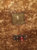
Cabinets came out pretty good, using nothing but sanding and tung oil. These really are substantial pieces of furniture.
Crossover not pretty, but works!
Had a helluva of a rattle with bass notes and realized I didn't put in all the screws. The pressure was actually flexing the back panel!
Crossover not pretty, but works!
Had a helluva of a rattle with bass notes and realized I didn't put in all the screws. The pressure was actually flexing the back panel!
Attachments


Cabinets came out pretty good, using nothing but sanding and tung oil. These really are substantial pieces of furniture.
Crossover not pretty, but works!
Had a helluva of a rattle with bass notes and realized I didn't put in all the screws. The pressure was actually flexing the back panel!
Beautiful
Biggles