• The move to the new server is done. There are some software and database maintenance updates in process. This has us passing the hat around to help out. We appreciate any donations. Seriously, even a dollar helps. The payment page may be found here - https://www.audiokarma.org/support.html

Canton Speaker Capacitor and Coil Reference Thread

Awesome. Thanks. It just seems to me that screws through the coil interfere with inductance. Besides screws or hot glue, what other methods are there to attach the crossover PCB to the cabinet? I will label all my internal wiring and be ready next week to start diagramming the crossovers. In two weeks should be able to completely remove the crossover and start doing some irreparable damage.
 
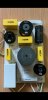
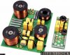
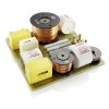
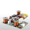
View attachment 2482613View attachment 2482616View attachment 2482618View attachment 2482619View attachment 2482621View attachment 2482622View attachment 2482623View attachment 2482625View attachment 2482626View attachment 2482627
This thread is amazing. I am extremely happy I found it. I have read the entire thread. Will read it again shortly. Thank you for identifying inductors 1025 and 1168. I have yet to identify 2 yellow rectangular caps (8402 and the other label might be obscured by the cabinet wall) and 3 inductors: 7808, 8392, 15842. I contacted Canton and Lukas was not helpful. He gave me no information and no reason why.

I have Canton Reference 3.2 DC, 9.2 DC, and Vento 866.2 center channel. I want to replace all caps, resistors, and inductors in all my speakers but will start with the 3.2s. :crazy:

What meters should I buy in order to test all the components? Multimeter, LCR meter, transistor meter, other? Any intro crosssover reading recommendations? The frequency response curve measured flat. So I am merely trying to replace the crossover like for like. I am not attempting to change the crossover schematic.

What do I need be mindful of? Common pitfalls? It looks as if the PCBs are thin and hot glued to MDF. What's the best way to remove without destroying the PCBs?

From the pics can anyone hazard a guess as to how much these crossovers cost retail? My goal is to create dream crossovers. I want to replace the 10µF and 12µF caps with Miflex caps but the cost was getting out of hand. I am also considering Jupiter Copper Foil instead of the Miflex but that would add $600 to the already bloated cost. I want to avoid electrolytic caps. Is it possible to replace the woofer caps with caps that are not electrolytic? Suggestions? Caps for the woofers are VAC. Substitutes are VDC. Is that problematic? Does voltage matter?

Following is a list of original Canton components. In parentheses are the replacement candidates.

Tweeter / Midrange
Canton Yellow rectangular cap (?)
Canton 8402 Yellow rectangular cap (?)
Resistor 10W1ΩJ (Path Audio 1 Ohm 10W)
2 Resistor 10W2.2ΩJ (Path Audio 2.2 Ohm 10W)
Resistor 10W33ΩJ (Path Audio 33 Ohm 10W)
Inductor 1168 0.25mH / 0.6 mm (Goertz CF.25 12 AWG Copper Foil)
Inductor 1168 3.3mH / 1.32 mm (Goertz CF3.3 12 AWG Copper Foil)
Inductor 15842 (?)
Canton MKT 1µ5 J 100 VDC (Miflex KPCU Copper Foil 600 VDC)
Canton MKP 4µ7 J 160VDC (Miflex KPCU Copper Foil 600 VDC)
Canton MKP 10µ J 160VDC (Jantzen Alumen Z 100 VDC)
Canton MKP 12µ J 160VDC (Jantzen Alumen Z 100 VDC 10µF +2.2µF = 12.2 µF)
4 Duelund 0.01 µF JDM Copper Bypass 600 VDC (not part of the original crossover)

Woofer
Canton 100 µF 35 VAC TF-F Bipolar 1664 (Jantzen Standard Z 400 VDC)
Canton 470 µF 23 VAC R-F Bipolar 6440 (Jantzen EleCap 100 VDC)
Canton 1000 µF 23 VAC R-F Bipolar 4340 (Kaisei Radial Non-Polarized Audio 25 VDC)
Canton BLM 7808 (?)
Canton BLM 8392 (?)
2 Resistor 10W68RJ (Path Audio 68R Ohm 10W)

For a low cost multifunction tester you can buy one of these types:
https://www.ebay.de/itm/Newest-3-7V-version-of-inductor-capacitor-ESR-meter-DIY-MG328-multifunction-test/272570921649?ssPageName=STRK:MEBIDX:IT&_trksid=p2060353.m1438.l2649
They may not be as accurate as an Atlas tester but for the money are hard to beat. I have compared the readings with my 2 Fluke meters and they were very close.

As Bijan said, you remove the crossover by removing the brass nuts from the 2 studs in the center of the coils. Note: being brass the studs and nuts have no effect on the inductance of the coils. When re-installing the nuts I paint a bit of fingernail polish over the end of the nut and stud to lock them in place.

All of the caps in your crossovers are MKT and MKP film including the yellow ones. If you look closely at the yellow ones you might find their values molded into the casing. Sometimes they are that way rather than being ink printed.

Some people will advise you not to upgrade the MKT caps, or to change the air-core coils to ribbon, or to upgrade the resistors. I am not one of those people. I am using Jantzen and Mundorf ribbon foil coils all through my crossovers, including the woofer section.
I also use Jantzen Silver-Z caps in the tweeter section, and Z-Standard everywhere else.
I am also using Mills and Mundorf M-Resist (Supreme and Classic). In my opinion they are better that what appears to be MOX resistors in your crossovers.

A couple on notes of caution:
Be careful concerning the resistance of the coils. Ribbon foil usually have a lower DCR than air core and if you lower the circuit resistance to much the coils can easily start to oscillate, and bad things happen after that. So you might need to plan on adding a small value resistor in series with the coil to maintain the same DCR as the original circuit.

I would be careful concerning adding bypass caps to foil caps. I did this, liked it at first, but with time noticed that the bypass caps added an effect to the sound that I did not like, something like a parallel signal slightly out of phase with the main signal. It did weird things to the imaging and I ended up removing all of the bypass caps. A 0.1µF or 0.01µF bypass added to an elco did not have any unwanted effects.

Have fun, but be aware that changing all of the components in the crossovers can make small changes in resistance that can change the voicing and balance of the drivers. You have to be ready to take a lot of time and make small changes to make the speakers sound their best. For this reason I made small external enclosures for the crossovers fitted to the rear of my speakers, allowing me to make changes in a few minutes without having to remove drivers to get at the crossovers.

Cheers,
James
 
For a low cost multifunction tester you can buy one of these types:
https://www.ebay.de/itm/Newest-3-7V-version-of-inductor-capacitor-ESR-meter-DIY-MG328-multifunction-test/272570921649?ssPageName=STRK:MEBIDX:IT&_trksid=p2060353.m1438.l2649
They may not be as accurate as an Atlas tester but for the money are hard to beat. I have compared the readings with my 2 Fluke meters and they were very close.

As Bijan said, you remove the crossover by removing the brass nuts from the 2 studs in the center of the coils. Note: being brass the studs and nuts have no effect on the inductance of the coils. When re-installing the nuts I paint a bit of fingernail polish over the end of the nut and stud to lock them in place.

All of the caps in your crossovers are MKT and MKP film including the yellow ones.

I'm pretty sure they not all MKT,some of them are MKP,they are labelled like that and people from Canton confirmed me. They using capacitors from Kemet/Arcotronics some of them are really good. I'm compared some Kemet MKP R75 4.7uf and they are really good. I know people who change Mundorf with Kemet MKP DC Link series in their crossovers.
 
For a low cost multifunction tester you can buy one of these types:
https://www.ebay.de/itm/Newest-3-7V-version-of-inductor-capacitor-ESR-meter-DIY-MG328-multifunction-test/272570921649?ssPageName=STRK:MEBIDX:IT&_trksid=p2060353.m1438.l2649
They may not be as accurate as an Atlas tester but for the money are hard to beat. I have compared the readings with my 2 Fluke meters and they were very close.

As Bijan said, you remove the crossover by removing the brass nuts from the 2 studs in the center of the coils. Note: being brass the studs and nuts have no effect on the inductance of the coils. When re-installing the nuts I paint a bit of fingernail polish over the end of the nut and stud to lock them in place.

All of the caps in your crossovers are MKT and MKP film including the yellow ones. If you look closely at the yellow ones you might find their values molded into the casing. Sometimes they are that way rather than being ink printed.

Some people will advise you not to upgrade the MKT caps, or to change the air-core coils to ribbon, or to upgrade the resistors. I am not one of those people. I am using Jantzen and Mundorf ribbon foil coils all through my crossovers, including the woofer section.
I also use Jantzen Silver-Z caps in the tweeter section, and Z-Standard everywhere else.
I am also using Mills and Mundorf M-Resist (Supreme and Classic). In my opinion they are better that what appears to be MOX resistors in your crossovers.

A couple on notes of caution:
Be careful concerning the resistance of the coils. Ribbon foil usually have a lower DCR than air core and if you lower the circuit resistance to much the coils can easily start to oscillate, and bad things happen after that. So you might need to plan on adding a small value resistor in series with the coil to maintain the same DCR as the original circuit.

I would be careful concerning adding bypass caps to foil caps. I did this, liked it at first, but with time noticed that the bypass caps added an effect to the sound that I did not like, something like a parallel signal slightly out of phase with the main signal. It did weird things to the imaging and I ended up removing all of the bypass caps. A 0.1µF or 0.01µF bypass added to an elco did not have any unwanted effects.

Have fun, but be aware that changing all of the components in the crossovers can make small changes in resistance that can change the voicing and balance of the drivers. You have to be ready to take a lot of time and make small changes to make the speakers sound their best. For this reason I made small external enclosures for the crossovers fitted to the rear of my speakers, allowing me to make changes in a few minutes without having to remove drivers to get at the crossovers.

Cheers,
James

I was thinking of getting the Fluke 87-V. Once I finish the speakers I wanted to make one power cord and 4 interconnect cables. The 87-V should be able to handle all of this right?

Thanks for the information on the capacitors and inductors. Have you used any copper foil capacitors with any Canton speaker? I am really interested in how it would change the high frequencies of the ceramic aluminum oxide tweeter. And how copper foil inductors affect aluminum midrange and woofers. Starting to get a little excited.

Did you have issues with both 0.01µF and 0.1µF bypass caps? The parallel, out of phase signal sounds like an echo. Paper cone drivers are notoriously anti-resonant. A friend did not have issues using bypass caps but he had neither Canton speakers nor aluminum drivers. I was under the impression that really large caps usually need a bypass cap especially for high voltage.

Thanks for all the warnings. Will take special care when I start the work. Will take many notes, label everything, diagram and understand crossover before starting the work. Looking forward.
 
Can you tell me why some put cople of capacitor with same value in parallel? What is achieved with that? View attachment 2482961

Is this pic really 1.2 DC crossovers? Is it me or are these crossovers not impressive? The 1.2's were top of the line. Shouldn't the crossovers be very impressive? I am not impressed at all with my 3.2 crossovers. Are my expectations unrealistic? Do you get superb crossovers only in $20k speakers?

What type of input/output terminals are these? Screw on?
 
Is this pic really 1.2 DC crossovers? Is it me or are these crossovers not impressive? The 1.2's were top of the line. Shouldn't the crossovers be very impressive? I am not impressed at all with my 3.2 crossovers. Are my expectations unrealistic? Do you get superb crossovers only in $20k speakers?

What type of input/output terminals are these? Screw on?
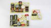
ofc566p96870.jpg
This is from Karat Reference 2 DC.
For my point of view it is ok, ICW capacitors,ok resistors,ok inductors.
I think they put good comments. If you look other manufacturers you will get a point what i said.

I'm looking some Gauder Acoustic speakers recently, they produce really hi-end speakers from 4000$ to 250000$,and this is crossover from their 33000$ speakers:
9._Berlina_Weiche_RC_7_BE_Gesamt (1).jpg
They work with stiff material drivers,aluminium,ceramic, diamonds, like Canton. It's hard to manipulate with this drivers because they ringing but result is really good.
I asked mr. Gauder abouth using ceramic resistors vs MOX he said they diling with mathematics and physics not "hokus pokus".
I totally understand but my question was physical...
Someone cutting costs someone don't see needing.
In many crossovers Canton put a bypass MKT capacitor with that large one 1000uf from DC(Displacement Control) network. In case of that Ergo 700/702/607 pictures It's a 18uf MKT.


That connection in your crossover and other better Canton is screw mounting cables.
 
@BijanBojan Thank you again for the pics. Very thoughtful. I very much appreciate it. I think that I just don't know enough to understand what a really expensive crossover looks like. Take a look at https://www.humblehomemadehifi.com/assembly.html. Those are small assemblies but they look expensive. Look at the Jantzen Amber Z cap crossovers. Those are $3,000 crossovers. When I see 1.2 DC or 1K, that's what I expect. Clearly I am wrong. Maybe the expensive crossovers are in $100,000 speakers only! :rflmao:

I am diagramming one of the crossover collages you posted with XSim. I think it's a good practice exercise before I open my speakers up again to diagram my crossovers. I might put all copper foil caps on my tweeter and midrange to see what the best really sounds like. Might as well because I don't ever plan to modify these speakers again. Ever.
 
Last edited:
Hello! Im new to tis site.
Im working on a Canton GLE 430.2 and I need new capacitors. Been searching all over but I cant find any place to buy them.
Anybody that can help?
No 1 is 4,7 µF 35Vac 1882
No 2 is 6,8 µF 23Vac 3779
No 3 is 8,2 µF 23Vac 2374
After reading all the pages in this tread I am thinking of trying the Jantzen cross cap that was linked to in another page but I`m a bit confused about Vc and Vac. The once that is original on the Canton crossover is 35Vac and 23Vac. The jantzen is 400Vc. Can I still use them?
 

Attachments

  • 1645556670287.jpg
    1645556670287.jpg
    71.5 KB · Views: 17
Last edited:
Hello! Im new to tis site.
Im working on a Canton GLE 430.2 and I need new capacitors. Been searching all over but I cant find any place to buy them.
Anybody that can help?
No 1 is 4,7 µF 35Vac 1882
No 2 is 6,8 µF 23Vac 3779
No 3 is 8,2 µF 23Vac 2374
After reading all the pages in this tread I am thinking of trying the Jantzen cross cap that was linked to in another page but I`m a bit confused about Vc and Vac. The once that is original on the Canton crossover is 35Vac and 23Vac. The jantzen is 400Vc. Can I still use them?

You can totally ignore that lable 35vac and 23vac. You can buy capacitors from 100V to 1000V, there is some practice to put capacitors in range of 250V to 600V, in my crossovers i put 47uf 900V.
Capacitors you need are small values and they shouldn't be expensive. Just put MKP from good company (Kemet, Vishay,Janzen,Mundorf...)
 
For a low cost multifunction tester you can buy one of these types:
https://www.ebay.de/itm/Newest-3-7V-version-of-inductor-capacitor-ESR-meter-DIY-MG328-multifunction-test/272570921649?ssPageName=STRK:MEBIDX:IT&_trksid=p2060353.m1438.l2649
They may not be as accurate as an Atlas tester but for the money are hard to beat. I have compared the readings with my 2 Fluke meters and they were very close.
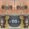
Two meters from EBay arrived this week. I got the DER DE-5000 LCH meter. I was able to mod the DE-5000 by replacing the baby T-Rex alligator clips with Kelvin alligator clips. I haven't soldered anything in 10 yrs so my soldering was not pretty but the DE-5000 calibrated successfully on the first try. As an added bonus I found the Fluke 87V for 40% off. Just too good to pass up.

I have a label maker and numbered stickers to label everything to prevent mistakes on reconnecting the drivers and crossovers. I have my next hurdle, how do I open up the speakers again to work on them? I want to buy some sort of work bench or saw horse. Perhaps two handscrew clamps on the back of the speaker then lie it down flat on the clamps on the floor. The sides of the speakers are curved with the front baffle 10 inches wide and rear 5 inches. Each speaker is 110 lbs so it's an odd shape with a piano gloss finish. Not very heavy but certainly unwieldy.

Is it possible to test a signal through the old crossover before I disassemble to compare with the new crossover?
 
A friend suggested Jorgensen 10-inch Adjustable Handscrews to hold the speakers. How can two 1/4 lb clamps hold a 110 lb speaker? The clamps work amazingly well. I disassembled a speaker and disconnected the crossovers. All the parts are really high quality. Even though the crossovers are small, they are pretty heavy due to all the copper. I still am learning to diagram the schematics. I will start diagramming tomorrow. Feel free to help.

Both crossovers together measure 11 x 6 x 2 inches. Available space is 19 x 6 x 5 inches. That space is dissected by a brace. Still I can fit 2 large crossovers in that space. I will diagram the largest crossovers I can fit inside the cabinet. I will then see what's the maximize size I can get for external crossovers.

I wanted to mention that a friend upgraded his crossovers and talked incessantly about it. That's what gave me the idea. He has Tekton Speakers. I joined the Tekton owners group on Facebook. They talk quit a bit about upgrading crossovers. One post mentioned the "High-end loudspeaker crossover upgrading" group. I joined. That group mentioned the "Duelund & Mundorf Fanatics" group. I joined that as well. Both groups are amazing with some ridiculously beautiful upgrades and valuable suggestions. I am actually considering making external crossovers just from the extremely high quality content from these two groups.

Thanks so much for all your help. I could not have gotten this for without this forum.

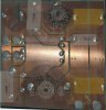
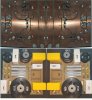
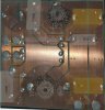
woofer-collage.jpg woofer-pcb-merged.jpg tweeter-midrange-merged.jpg tweeter-midrange-collage.jpg
 
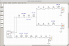
Diagramming schematics is a lesson in logic if you have not done it before. This has been an amazing project. I had to take an engineering course at Khan Academy in circuit analysis. I needed a basic understanding of nodes, branches, loops, and meshes. Once I understood what a mesh was, it allowed me to label each of the meshes. I then listed each part of that mesh. Then starting from the output trace it back to the input. Unfortunately for 2 days I tried to trace starting from the input. Of course the input is connected to EVERYTHING. You have to trace in reverse from the output back to the input. Now I will dissemble and measure each components. Assuming the labels are correct, there are 5 components with no label. Once I complete my measurements, I will update my schematic then start shopping for Jupiter and Miflex upgrades.

L1 (BLM 8392), L2 (BLM 7808), L5 (Canton 15842), C5 (Canton 8402), and C6 (Canton 8402) are all estimates based on size. I have to desolder then measure each. I know these 5 values are off because the FRC in XSim has a hump at 2000 to 3000 Hz. I had the speakers measured 3 weeks ago and the FRC was flat.

C1, C2, and C3 are electrolytic capacitors. Can I replace them with solid foil caps? How would I do that since solid caps usually measure 0.1 to 12 µF. These caps measure 100, 470, and 1000 µF. The change will clearly affect the FRC. I will also add at least 2 Duelund bypass caps. They are currently not on the diagram.

Do you see any errors with my logic or diagram?

tweeter-midrange-merged-mesh.jpgcanton_3.2_dc_speakers.png
 
Last edited:
Oh...yes,i think i see a lot of errors in your schematic. I will try to draw it for you
If you want to replace big electronic capacitors with MKT or MKP you need to connect many of them in paralel. You can see some MKT/MKP capacitors on Mouser,Farnell and similar sites
 
Back
Top Bottom