richardloh
Active Member
After several on/off, 33rpm to/fro 45rpm as well as variable to/fro normal, all seem fine still after 24 hrs powered up and running nonstop.

Last edited:



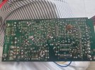
Definetly the PCB# is the same, in all production years, but they did variations. The loose PCB is for sure the latest. In my older PCB I have the 3 caps mounted, with C30 named C26. The SM available online should cover the first and middle production years: in the newest PCB D1-2-3-4, on K263, cancelled D2-4, but are still present in the schematics. And so other components......Ah, in the older PCB, a capacitor of 2200pF is mounted on TR1 and TR2, solder side of K264 board.
Hi Claudio,
No, I did not do any change to PC613 .. only thing I did was the recap of all the e capacitors of these "loose" pcba with the ebay kit while getting 4.7uf 400v vs stock 250v in addition for the known under rated strobe related one that many found to have leaked and then started in the abovementioned pbca swap.
Somehow missed the mentioned double value resistors note in the schematic but the following photos shows that capacitors are populated differently and in different values/size w.r.t. c25 or c30 in the ku-263 units while I have no clue if electrically the same i.e. different versions with varied capacitors to "match" board variations in addition to your finding of double value resistors.
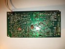
I did tried briefing to look at version # on the pbca but missed them .. the jap seller of theses loose pbca claimed that they were newer version but perhaps for dp-80 where they were from and not version # on pbca themselves.
Cheers.
PS: Both original and "loose" infamous red/black wires are similarly swapped on ku-263
View attachment 3291506View attachment 3291508
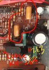
This is mine, with 2 caps in the back:Hi Claudio,
I have only 1x 2200pf on TR1 on original ku-263 (not ku-264) as shown in photo and also shown in most if not all the repaired board of the mentioned japanese blog i.e. nothing on TR2.
Btw, what is your trouble and how you had arrived on SC3120A of KU-264 being one likely cause ?
Cheers
Btw, what is your trouble and how you had arrived on SC3120A of KU-264 being one likely cause ?
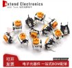
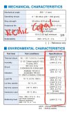
Richard, VR1-2: pay attention on its substitution. If they are not stable, in time and with varing temperature, they will change resistance value causing a not optimal speed adjustment.
With them, R36-37 are also important: the choosing is for low PPM, 50 or less.
Since 33rpm adjustment is depending on 45rpm one, that is the signal passes through VR2-R37 before reaching VR1, I made on my DP80 an improvement, in my opinion, substituing VR2-R37 with a fixed low ppm resistor.
The same can be done with VR1-R36, but it's time consuming to find the optimal value.
To sum it up, good low ppm trimmer are the way to go. Forget about top and bottom adjustment.....the Jap showed the way to go!



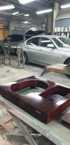
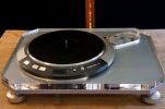

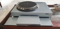
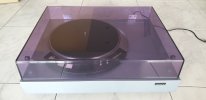



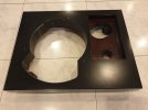
Nice ! Photos pls but dun think will have 3rd dk300 and I do like the silver trim of dk-200 being modded similarly to mount the stepdown xformer... lolA compromise, I've been very pleased with semigloss black.