

You are using an out of date browser. It may not display this or other websites correctly.
You should upgrade or use an alternative browser.
You should upgrade or use an alternative browser.
Dynakit ST 70. A Restoration Journey
- Thread starter Stereodiver
- Start date


Something doesn’t sound good, if you are measuring vastly different voltages on the screen taps (pin 4) of the output tubes. What are you measuring on pin 3 of each tube (the plate)? If you could put the voltages for each pin in a table for each tube it would help.The chart I have says I should have 400 to 435 VDC. On the left V6 425. VDC. V7 178 VDC.
the right V3 190 VDC. V2 426 VDC. Notice how they crisis cross.

Stereodiver
Well-Known Member
I measured all the EL 34’s pin 4. The “V” designation comes from the assembly manual.
Left channel V6 425 vdc. V7 178 vdc
Right V3 190 vdc. V2 426 vdc
I printed a chart that someone here posted that says I should be getting 400-435 vdc on pin 4.
Left channel V6 425 vdc. V7 178 vdc
Right V3 190 vdc. V2 426 vdc
I printed a chart that someone here posted that says I should be getting 400-435 vdc on pin 4.
Stereodiver
Well-Known Member
I will try to make a chart tomorrow and get everything listed for you guys.
Thanks a bunch and stay tuned! Mark
Thanks a bunch and stay tuned! Mark
Yes, the plate voltages on pin 3 should be 410 Vdc and screen voltage 415 Vdc on pin 4 for each EL34.
Thanks for listing the pin 4 voltages. Could you do the same for pin 3, please? Also the B+ at the center tap of each output transformer. Maybe a full chart is not needed right now.
Thanks for listing the pin 4 voltages. Could you do the same for pin 3, please? Also the B+ at the center tap of each output transformer. Maybe a full chart is not needed right now.
Last edited:

One other thing you may want to post. Your actual outlet voltage VAC — the one the unit is plugged into.I will try to make a chart tomorrow and get everything listed for you guys.
Thanks a bunch and stay tuned! Mark
Thanks!

Stereodiver
Well-Known Member
@Mr Boochie @spantou01 Here ya go guys. Let me know if it’s legible enough.

The voltage from the wall is 120vac As you can see I also included the voltages on the rectifier and quad cap. The rectifier looks OK I guess but the quad cap looks off also. I do have the higher capacitance quad cap installed.
please look it over and let me know what you think. As always, Thanks!
The voltage from the wall is 120vac As you can see I also included the voltages on the rectifier and quad cap. The rectifier looks OK I guess but the quad cap looks off also. I do have the higher capacitance quad cap installed.
please look it over and let me know what you think. As always, Thanks!
I rotated the photo for us non-Emu types. 
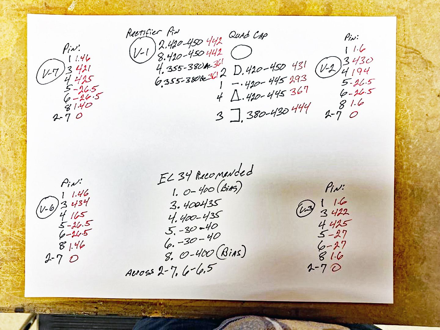
Now, to be sure.
V1 = GZ34
V2 and V3 = EL34 (push-pull pair on the top of the schematic?)
V6 and V7 = EL34 (push-pull pair on the bottom of the schematic?)
Any measurements of the 7199 tubes?
Thanks!
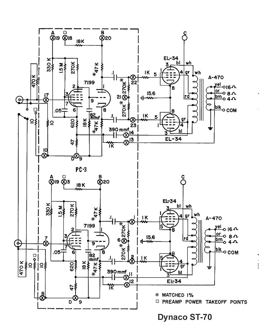
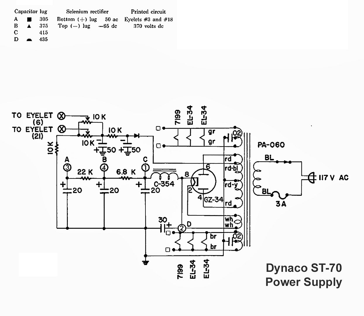
Now, to be sure.
V1 = GZ34
V2 and V3 = EL34 (push-pull pair on the top of the schematic?)
V6 and V7 = EL34 (push-pull pair on the bottom of the schematic?)
Any measurements of the 7199 tubes?
Thanks!
Upon initial look at the voltages, there is something amiss with the V2 and V4 screens (pins 4). Recheck your wiring from the output transformer to the screens.
Good lucK!
Good lucK!
Yes, good advice @Mr Boochie.
The B+ (after the choke) looks a bit high, but not seriously so. I’m not sure what new quad cap values you installed, I assume 525 V or higher. The manual says B+ should be 415 Vdc; try to get that. Be sure to use a 30 uF tap directly after the rectifier and before the choke. The one after the choke could be higher capacitance.
Something strange is going on with V2 and V6. I assume you have switched EL34 tubes already and the problem stays with the same sockets. Make sure the output transformer wires are correctly identified and used. Then carefully check the wiring and socket connections for V2 and V6 between the respective output transformer’s screen taps and pin 4. Do the same for the plate taps and pin 3. The voltage you measure on pin 4 are obviously too low.
The question is why. I also noticed the plate voltages on these two tubes are basically sitting at B+, close to the voltages you would expect for the screen UL taps. Are the screen and plate wire possibly switched on these tubes? But then, why are the “other connections” now used for screen, that much lower. Don’t know yet.
If all this checks out fine the next step will be to get some resistance measurements between the all taps on the primary side of the output transformers (measuring from the center tap) to make sure there is no problem there. Be care! Turn off the amp, unplug the amp and make sure the caps are all fully discharged before measuring resistances.
Last edited:
Stereodiver
Well-Known Member
To answer your first question. Yes V1 rectifier. The others are the EL 34’s. No, I did not do any measurements on the 7199’s.
The tube sockets are wired as the amp came to me. I did check and they seem to match the assembly instructions. I will double check!
The tube sockets are wired as the amp came to me. I did check and they seem to match the assembly instructions. I will double check!
Stereodiver
Well-Known Member
When I installed the quad cap I followed these directions. If I remember correctly I did need some more clarification from Pio 1980 and I believe we communicated via PM. In my records I have a hand drawn schematic that I followed. The way it’s wired now is vastly different than what the assembly instructions show. Even the resistors span different terminals.The quad cap, if the increased capacity replacement, should be wired so that the 40uF section is first in the string from the rectifier into the choke. Then the 80uF on the output end of the choke to the output transformer and dropping resistor to the 30 uF, then the second dropping resistor to the 20uF section. 40uf, then 80, then 30, then 20.
The 1.2 meg resistors provide a more favorable relative voltage distribution for the driver tube than the 1.5 meg. The driver tube screen voltage affects all other voltages around the driver tube, except of course, the heater, which ideally should be 6.3 VAC +- 5% across the heater lines.
Could a mistake here be causing me seeing wrong voltages on the output tubes?
You need to be careful. I've missed mis-wiring issues, as it is sometimes hard to see within the "spaghetti." Check for soldering blobs that might be causing issues.To answer your first question. Yes V1 rectifier. The others are the EL 34’s. No, I did not do any measurements on the 7199’s.
The tube sockets are wired as the amp came to me. I did check and they seem to match the assembly instructions. I will double check!
Good luck!
Please post close-up photos of what you did. The resistors should not be spanning different terminals.When I installed the quad cap I followed these directions. If I remember correctly I did need some more clarification from Pio 1980 and I believe we communicated via PM. In my records I have a hand drawn schematic that I followed. The way it’s wired now is vastly different than what the assembly instructions show. Even the resistors span different terminals.
Could a mistake here be causing me seeing wrong voltages on the output tubes?

I don’t expect the main issue to be PS/quad cap related. There could be a mistake, and the resistors should not be spanning different terminals, but the voltages you posted for the quad cap above look much closer to where they should be, than the voltages on pin 3 and 4 for V2 and V6.Could a mistake here be causing me seeing wrong voltages on the output tubes?
Stereodiver
Well-Known Member

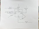
Here is a pic of the Quad Cap Installed. The next is my hand drawn schematic.
Hopefully it's clear enough. The half circle is 80uf. The square is 40uf. The triangle is 30uf and the blank is 20uf.
Stereodiver
Well-Known Member
I just double checked and the tube sockets are in fact correctly wired to the output transformers.
Your PS voltages look acceptable to me, at least at this point, if you have the 40uF after the rectifier, then the choke, then 80 uF, then 6.8k resistor to 30 uF and finally 22k to 20uf.
If your sockets are in fact correctly wired to the output transformer primary wires I think next would be the resistance checking of the primaries, as described in post #190.
Edit: I just noticed in you photo in #196 a small blue-bodied resistor going to pin 4. Did you install screen stopper resistors? I did not catch that earlier that you modified a bit from the original. Are these resistors intact and of correct value in V2 and V6? If it is too high a value it could explain why your screen voltage is low.
Last edited:
Stereodiver
Well-Known Member
@spantou01 @Mr Boochie You guys are the best! I swapped the tubes and get the same results. Up until this point in time I've been landing my probe on the pins.
spantou01 You hit the nail on the head! Yes. Those are Screen Stability resistors I installed per @dcgillespie. 100 ohm 1/4 watt Xircon metal film.
I just measured the voltages where the wire connects to the resistor and I get the proper voltages EVERYWHERE! Than, guess what? At the two places where the voltage is low, the resistors test "OPEN"! The other two test correctly. Crap!
So I guess the next question is... A, why did the first resistor burn? B, what made the other two go open? Replacing them is easy. I have more. Not that I do this a lot but I've never had a resistor fail like that without a reason.
Any ideas why they went open? If you can't think of why, should I up the wattage to 1/2 watt?
Thanks again guys! Mark
Hi Mark,
That’s great news!
I can’t think why they blew, but 1/4 watt may a bit low in wattage for transients, although they will provide extra protection. The EFB SCA-35 with Dave’s boards uses 100 Ohms 1/2 watt screen stability resistors, and that is probably the smallest I will go with.
Good luck and happy listening.