• The move to the new server is done. There are some software and database maintenance updates in process. This has us passing the hat around to help out. We appreciate any donations. Seriously, even a dollar helps. The payment page may be found here - https://www.audiokarma.org/support.html

Dynakit ST 70. A Restoration Journey

…..say Selenium Rectifier. I also dont want to loose the “Soft Start” aspect. I know there are many opinions about it. I’ve read both good and bad things about them. Right now I see no reason to change it. If it blows,,, I’ll cross that bridge when I get there.

“If it ain’t broke, don’t fix it”.

Mark
I had always taken it as gospel to replace the Selenium rectifier. Would be interested to know the pros in keeping it. How does the selenium rectifier relates to “soft start”?

When it blows you better have a correctly functioning fuse installed, else you may loose some valuable parts.
 
I had always taken it as gospel to replace the Selenium rectifier. Would be interested to know the pros in keeping it. How does the selenium rectifier relates to “soft start”?

When it blows you better have a correctly functioning fuse installed, else you may loose some valuable parts.
I usually replace selenium diodes, just as a habit. They tend to be old. Like 1950s era old. But, a good working bias supply places very little stress onto the diode. For this purpose, the selenium diode prolly would last 100 years or more. :)

If they do bust, for whatever reason, the selenium oxide left behind on the chassis can be considered a biohazard --- but in reality, only in very large amounts, not those seen in a diode.

A 1N4004 or UF4004 is an adequate replacement. I use UF4007, since I have a lot of them. :thumbsup:
 
Last edited:
The selenium has nothing to do with how it starts.

The reason people say to replace it is that as they fail the output voltage drops and eventually they can die and the bias supply stops working. The thing is though, selenium mostly only fails when worked to its current limit, either by design or from bad caps. In this its being asked to do very little. If the caps are good its working well below its stress level so its not really failure prone. No special advantage to keeping or replacing it honestly, just be aware that you might need to bump the value of the first resistor off the rectifier before the pots in order to compensate for the higher output voltage.
Thank you for correcting me!
 
Yes, old, dried-out electrolytic caps can lead to catastrophic failure in your amp. Any 'lytic older than 30 years old, should be replaced. Whether the unit was used or not.

:beerchug:, :thumbsup:, :bigok: !
As the original 60 + yr. old dying main and bias electrolytic filter cap(s) start electrically leaking internally (and they most certainly are !) this will increase the current draw through the power transformer, both the high voltage, bias, secondary`s, and primary windings, thus needlessly stressing them and if continued use of the amp will most likely cause the power transformer to fail !
 
Concur on the great job comments above.

If I recall my last ST-70, the bias on one channel went off the rails so I went ahead and replaced all the coupling caps on the board. Left it original other than that. I guess what I'm saying is if the bias is solid, let it be, at least for now.

I never replaced the selenium rectifier on my amps either. Some people make it sound like if one blows poisonous gas will kill your cat and anything else in a 2ft radius, but I take my chances.
 
Last edited:
Snow has fallen in my neck of the woods so it was time to get back to it! Plus, I have a pretty good reference on how it sounds to this point in time.

Here‘s what I started with.
707D273C-4475-4D97-B659-BE63772A2D6C.jpeg
The stock board.

First off, change the caps.
24C5AA1E-4A3D-4FEA-B4AD-E4B3434DC014.jpeg
I chose these Jupiter caps from Antique Electric Supply because they seemed to get good reviews. And, I liked that they say, “Vintage Tone”. For the PF values I used the ”Silver Mica” ones from the same place.

I was going to stop here and give it a listen for a while. I did kinda want to hear any changes before replacing the resistors. That way I could report on how each would impact the sound. But,,,,
I was having too much fun! So I went ahead and replaced the resistors too.
3914DCAA-F389-44C0-AB43-5AD8DFD14888.jpeg
PRP 1% metal film from a place called “Sonicraft”. A little pricy, but not a budget buster.

I have read that some people complain the stock board is difficult to work with. Reports abound about lifting doughnuts while removing parts. I’m happy to say I had no trouble whatsoever! Using my Stahl vacuum desoldering/soldering station, set to 550 degrees, I was able to open up the holes big enough to drive a train through! Leaving all the doughnuts firmly attached to the board. It actually was a pleasure to work on. Plenty of room between components. Almost no possibility of creating any solder bridges unlike other boards I’ve worked on.

The solder side of the board
C591A5FD-7F45-45A0-8CC8-9C818E477B68.jpeg

After completing the work I checked the bias and found that I had to turn it down quite a bit. I did have it set at 1.56v before starting this work. Checking it after the work I found it to be as high as 1.8v. I started to worry I would not have enough range on the pots because it was already on the counterclockwise side of the midway point of the pots. Not to worry though, a small tweak counterclockwise and it went right back down to 1.56v. It also seemed to drift less. Staying between 1.563v and 1.558v or so.

And lastly, the replaced parts shot. Gotta have one of those!
97F016CE-4A0D-44E3-8AA6-597307696FE4.jpeg

This did take the better part of the whole day. The difference between an amateur and a professional is the speed at which he does his work. I am an amateur!

I did get to pump a few songs through it. My initial impressions is there is an increased “Presence” of a centered vocal. Seems to float between the speakers in a much more focused manor. Not that it was bad before, but definitely better now. In the bottom end the “Vintage Tone” written on the caps seems to be true! Much more tone on drum wacks than before. The “Silver Micas” also seem to be doing their job. On Buddy Holly’s song “Everyday” the chimes seem to have more sparkle, more “Tinkle”. Lastly, I’m very impressed with the shear power it displays. I was always under the impression that one needed at least 100 watts. This amp has dispelled that myth for me. 35 watts of EL 34 power is plenty!

All in all, I’m very happy with the outcome! This amp is definitely a keeper!

Thank You sincerely to all that have followed my Journey and to those that helped me along the way. (You know who you are). It’s time to put a few more hours on it and try to determine if “Cap Break In” is really a thing. LOL!

And,,, time to look for another project! Later, Mark

 
Very nice! It looks great. 35wpc is plenty in most cases.
I use my ST-35 a lot. Its only 17wpc and gets plenty loud.
Honestly I don't notice much difference in volume if any
between my ST-70 and ST-35. The difference is in the speakers used.
ST-70's just plain sound good. They sound great even without a preamp, just a volume control.
 
This amp did have a bit of mechanical hum from the power transformer from the git go. I did install rubber washers between it and the chassis, but that didn’t help much.

It wasn’t bad. I could not hear it from my listening position but standing above it with the amp at waist height you could hear it.

Since replacing the caps and resistors on the driver board the hum is almost all gone! I’m not smart enough to know weather replacing the caps and resistors caused the decrease in hum or if it is just because I’m using it more.

Any thoughts?

Mark
 
Yes. That was done before the work on the driver board. After replacing the bias supply caps and the multi cap the hum was still present. Replacing the caps and resistors on the driver board seemed to make a bigger difference.
 
The Journey continues. The other day I powered it up and within a minute or two heard crackling sounds coming from the left speaker. I looked over at the amp and lo and behold saw what looked like flames under the EL34’s on the left side. When I opened it up I found this…
1E4ECEAC-3E3C-4B39-B980-B06788518CFD.jpeg
This is the Screen Stability resistor that I installed per @dcgillespie.
I just tested the tube. At first it seems to test ok but within a minute or two the needle on my tester falls into the bad zone and than when testing for shorts it does indicate the tube is shorted.

My question is, do you think the shorted tube took out the resistor? Am I lucky enough that all I have to do is replace the tube and the resistor to get this thing to sing again? Or, do I have to look at other things?

Thanks in advance, Mark
 
My question is, do you think the shorted tube took out the resistor? Am I lucky enough that all I have to do is replace the tube and the resistor to get this thing to sing again? Or, do I have to look at other things?

Thanks in advance, Mark
A shorted tube or a bad instability has popped up in your output stage.

:(
 
Parasitic oscillation instabilities occur in amps due to an unexpected positive feedback loop caused by stray capacitance and/or inductance within the output stage.

A screen resistor helps dampen these unwanted oscillations and limits the current flow. However, if the instability increases, the current flow increases — to the point where the resistor may fail or "pop."
 
@Mr Boochie Thank you sir! Please understand that I’m just a hobbyist. Are you telling me that something else took out the resistor and the tube? So just replacing the tube and resistor isn’t going to fix it? Can you tell me exactly what and how to check.
 
@Mr Boochie Thank you sir! Please understand that I’m just a hobbyist. Are you telling me that something else took out the resistor and the tube? So just replacing the tube and resistor isn’t going to fix it? Can you tell me exactly what and how to check.
Parasitic oscillation is just one possibility. To narrow it down, you'd need a scope and signal generator—or, better yet, find a good tech.

It may not be oscillations. You'll find out when you replace the tube and resistor. Let sleeping dogs lie if all is well for a month or two. If that resistor pops again, find a tech.

Be sure the fuse in the unit is the proper one.

Good luck! :thumbsup:
 
Last edited:
@Mr Boochie I replaced the resistor and used one of the original tubes to test it out. I wasn’t able to get the bias up to 1.56 volts on that channel but I’m thinking it’s because the tube is too weak. It maxed out at 1.4 It played music for an hour or so and sounded Ok on my cheap test speakers.

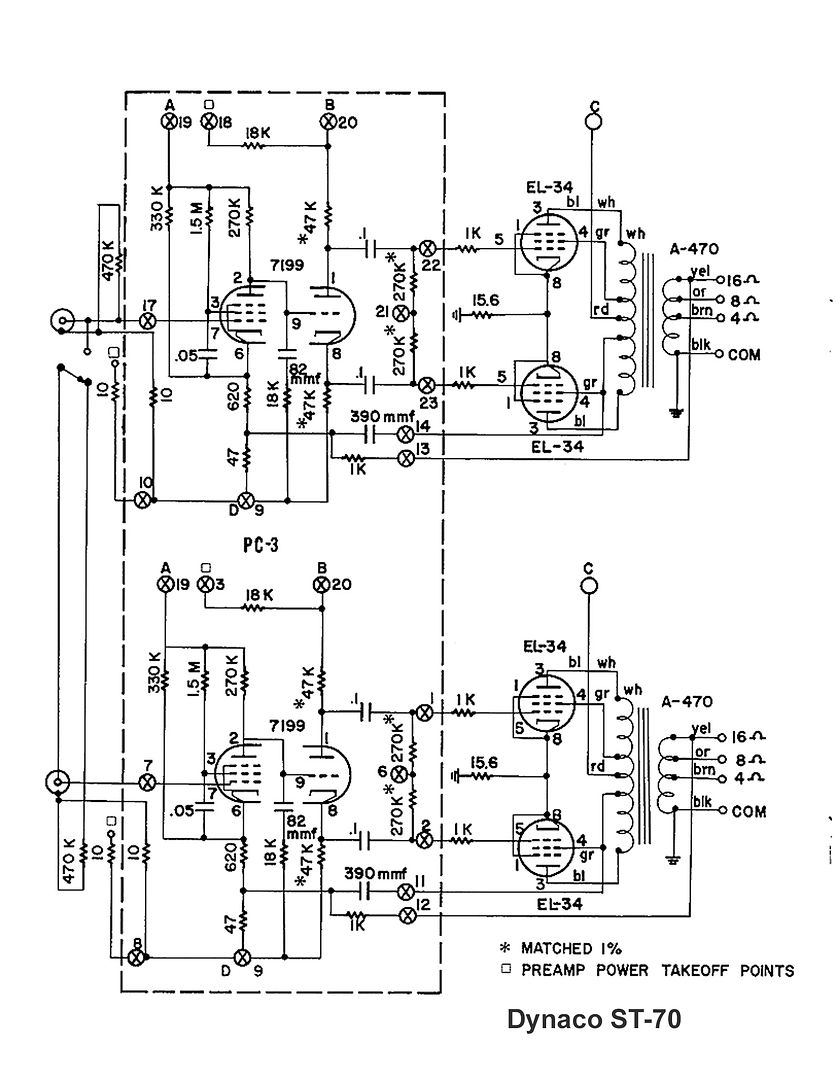
However, before I played music I checked the voltage on pin 4 where the resister is connected to. The front tubes are V-6 left and V3 right. The rear tubes are V7 left and V2 right. The chart I have says I should have 400 to 435 VDC. On the left V6 425. VDC. V7 178 VDC.
the right V3 190 VDC. V2 426 VDC. Notice how they crisis cross. This is the first time I’ve checked these voltages. I don’t know if it’s been this way all along.
This doesn’t seem right to me. I’m hoping you have some insight.

Thanks, Mark
 
24e832bb-dda4-4707-b88e-182ea053cebf.jpg

To be sure, which tube and voltage points did you measure?

Thanks!
 
Back
Top Bottom