• The move to the new server is done. There are some software and database maintenance updates in process. This has us passing the hat around to help out. We appreciate any donations. Seriously, even a dollar helps. The payment page may be found here - https://www.audiokarma.org/support.html

Early Fairchild 412 build, including new plinth (photo heavy)

adnick

Addicted Member
Just finished a plinth build thread for a Russco Studio Pro which went better than expected, so figured I’d press my luck and do a thread on this Fairchild.

The Russco plinth is for a professional model idler drive, it actually belongs to @BillWojo, he specified the size and I did the design build, it can be viewed here:

https://audiokarma.org/forums/index.php?threads/russco-studio-pro-plinth-build.966246/


This Fairchild is a very early model 412 basic #238, wide belt cover, deep body with bottom plate, pop up 45, 45/33 platter.

@Sam Cogley has put together an official Fairchild 412 registry thread, and he outlines the difference between models: https://audiokarma.org/forums/index.php?threads/the-official-fairchild-412-registry-thread.677977/

Fairchild was an amazing individual and and one of his companies produced very high end audio equipment.

In my opinion these tables are extreme bargains still, in its production time the 412 was one of the most expensive turntables available, probably only surpassed by EMTs.

The 412 is the only belt drive turntable, that I’m aware of, which was used as a broadcast table.

Have been looking for one for a long time and this on fit my criteria, needs work and a plinth ;)

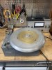
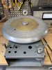
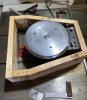
Here’s the project:

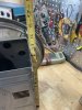
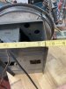
4793447E-3C3D-41DB-9411-C0A877ABA604.jpeg B23F9F72-9D4A-4891-96DB-509FF3AA8958.jpeg

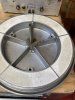
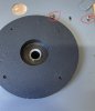
these are heavy platters with a 3/8” ball bearing in the shaft well and a concaved shaft, the platter is actually filled with plaster:eek:
48691CCC-C89D-4A96-AE04-F41F38CA3018.jpeg

An excellent design implementation; the shaft well is supported and attached to the heavy metal frame.
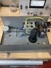
4856C84D-2D33-4D69-9C48-EA2FD240F80E.jpeg

Thankfully it’s in much better shape than I expected, so it only needed a cleaning, new motor mounts and new belts. @Sam Cogley sent me some new super motor mounts. The motor is completely suspended by the four bright blue mounts:
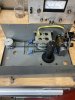
EA01460F-93C9-40B3-93D0-15715340935D.jpeg


@Sam Cogley informed me that the yellow wire cover becomes brittle and can vibrate fairly loudly, however this one is very flexible…Motor is very quiet.

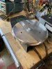
Here it is cleaned up a bit, ordered 2 belts and only received one, so that’s next on the list…
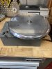
68CBFE1E-ACF3-4770-A363-B043035C2179.jpeg 2C41ABFE-0A4B-4EA1-B8D4-96C40A993AFC.jpeg
 
Register to hide this ad
I want to see your clock, must have 30 hours instead of 24 hours, I hardly find time to work on my projects, little here, little there and you plow through them.
Can't wait to see what you have in mind for this one, I'm sure it won't disappoint.

BillWojo
 
I want to see your clock, must have 30 hours instead of 24 hours, I hardly find time to work on my projects, little here, little there and you plow through them.
Can't wait to see what you have in mind for this one, I'm sure it won't disappoint.

BillWojo

Bill you caused me to laugh out loud physically, not something that happens very often ;) It’s perception, and like possession it’s 9/10 of the law:rflmao:

However my wife has an opposite perception, and my perception of myself is not as positive as yours :cool:

I’ll say thanks anyways,

Andy
 
Andy,
Something that goes missing from a lot of these "deep chassis" 412-1 / 412 "basic chassis" models that were designed for use with the electronic drive is the steel plate that goes across the bottom to make the structure rigid if the ED unit isn't installed. I can't remember from the listing if yours had it or not. If not, I can shoot you the dimensions. Only one of my two 412s had it installed, I've been meaning to make a replacement. On both your #238 and my #312, you can see the marks where the screws used to be in the paint on the outside of the chassis.

Nice Fluke multimeter, BTW. I have two of the IBM version, one of which I use constantly. I've replaced the handful of electrolytic caps in both of them, but one is still a bit erratic. I need to see about sending it back in to Fluke for calibration.

I'm really looking forward to seeing this build. You have the earliest documented 412! That polished platter looks great.
 
Last edited:
A very curious difference between your #238 and my #312 is the lack of a snubber cap across the power input on yours.

This photo looks like you have the upgraded pulley assembly. The original photos from the listing looked like it still had the original version.

Did the table come to you with screws and nuts through the motor mounts on the side toward the belt assembly? If they weren't there, I wonder if they were removed or if they were added between #238 and #312. They're used to compress those two motor mounts to adjust the angle of the motor. They're almost impossible to install with the chassis-side bracket installed, which is why, I think, that bracket was screwed in place instead of spot-welded.

If your power switch is a toggle with a ball on the end instead of a knurled rotary switch, it's correct for a very early 412. When I first got mine, almost every 412 owner said the switch was incorrect, despite the fact that the wiring looked like it had never been disturbed. Looking for other early 412s with the same switch is what started the registry thread in the first place.

The belt cover you have is the "deep" version, designed for use with the 412-1 in broadcast desks and custom plinths, and it was mandatory with the 412-2 and 412-4. On those models, a rotary knob that looks just like the "Fairchild" decal with the red dot replaced the decal as the speed selector. There was a shallow "butterfly" version that was made to use on 412-1s installed in the walnut and white factory plinth.

I'm going to send you some photos along with the scans of the owner's manual, which I realized I had never scanned when I went to send it to you. I'm going to add some of them to the registry thread as well for future reference.
 
Sam:

Thanks so much for the info and photos, really appreciate it!

Yeah that old Fluke is the meter I judge all other by….Fluke should reintroduce them, they are that good, and like you said, generally easy to repair.

The motor bracket had two rubber mounts close to the electrical stuff, but no bolts or screws….was wondering about the absence of bolts, but it seems to operate fine, however o only have the short belt,(that missing belt is a story in itself)

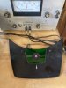
Note to those that need to replace motor mounts, remove the brackets by removing the screws on the top, might seem self evident but just in case:) the screws are circled in red, and there are another set for the other bracket, there’s also some fine belt adjustment via the oblong holes:
3D5ED7B1-42B9-4191-BEF9-AA88CAA1AC2A.jpeg


It has the original power switch, unfortunately the green plastic is cracked and it tore the knob sticker:(

6F4F54C3-58A5-423E-8FEE-60D967FC9C21.jpeg

Thankfully the bottom plate is there, :thumbsup: and that’s a very clever design, to support the shaft well with the structure.
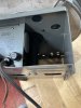
Here’s a photo of what we’re talking about, hard to see the black well, but the 2 screws that are close together in the center, screw into the bottom of the well.

Have worked on a later model 412, what’s known as a shallow body small belt cover, didn’t know these deep body had this feature, it’s certainly a big plus in my book :cool:
334DF98C-8674-4E0D-B6A3-35C0B3711E4A.jpeg

That’s interesting about the custom walnut plinth, this one had a walnut top that was cut for an SME arm but it looked like veneered particle board so I chose to leave it.

The belt pulley shaft appears to be in very good condition, just oiled it up and think it’s going to function appropriately.

I’m going to look into the electronics a bit more later on, will let you know….
 
From here, the pulley assembly definitely looks like the later version. If the section that screws to the chassis looks like Zamac and not aluminum, and the spacers above and below the rubber parts are metal, it's definitely the later one.

That bottom plate gets lost from quite a few of the "deep chassis" 412s that were made for use with the electronic drive unit - the ED attaches to the basic chassis where the bottom plate would be. I've seen a grand total of one of those, and considering the serial number on it, my assumption is that the production run was vanishingly small. It took the price of an already expensive turntable into the stratosphere. That particular 412-4 was sent out by Fairchild as a warranty replacement of a 411 that had gone wonky and couldn't be repaired.

That sticker should be fairly easy to replicate. I'd scan it and try to clean up the artwork, but my large belt cover is missing that piece of plastic entirely. I have one rather beat-up aluminum "butterfly" cover that I'm going to use as a pattern to make a couple of them for my two 412s. I'm not really sure why custom installs of the single-speed 412 used the large cover instead of the butterfly. There's no real need for it unless you're dealing with the extra bits of the 412-2 or 412-4. That's also why it has that white arrow on it - it points to the selected speed. The extremely rare 411 used the same cover.

On the electrical side, the motor is only supported by the flexible mounts. On the opposite side, it typically has the screw and nut through each mount that compresses them for adjustability. You may have also noticed that the belt pully assembly is an eccentric mount to adjust belt tension. For something as deceptively simple as the 412, Fairchild engineered the hell out of it.
 
The green plastic portion looks simple enough to fabricate, believe I’m going to do one in ruby red just to be different :rolleyes:

Going to follow Sam’s suggestion an scan the decal, but that’s a later to do item…

Trying to decide on a plinth design, one thing I’ve noticed in other wide belt 412 plinths, is that the belt cover is almost always to the left or right when standing in front of the table.

Here’s an example from @rocket_no9 photo of his 412:

CB21AA24-8B89-47F4-866F-1E644F571258.jpeg


That’s a fine looking table but I’m gonna do something a bit different :confused:

My design will have the belt cover facing to the front…

The actual metal frame is not that large, but one has to consider which arm or arms will be used, and tend to always build for 2 tonearms when doing a plinth for myself:

039ED657-55A4-400F-91FA-354765240D5F.jpeg


94807D41-B207-4B83-B713-C453BED42593.jpeg
0A07B8F9-1508-4384-B63B-E9DE67F2197F.jpeg
 
While waiting on a long belt to arrive, my attention is turned to plinth design. These deep chassis Fairchild’s are in a very solid structure with a lot of thoughtful design implementations so I’m not too worried about construction of a heavy layered plinth….but that could change ;)

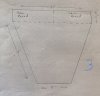
As stated above my intent is to have the belt cover facing the front. With that in mind I’ve drawn up some rough ideas, these are footprint designs and they are to a relative scale; the other driving criteria was, no rectangular box:rolleyes:

Don’t worry if you don’t like any of them, no lumber has been cut yet,:) haven’t even decided what type of wood to use yet….

E6DBC3E7-F573-4AEE-BBFD-16ACC0EE9AAB.jpeg F46C5D92-1C6F-4F9B-BA46-7F7BE1AFDA68.jpeg 3D234456-21C2-4B1E-B2A1-060856D4714A.jpeg
 
Last edited:
Wow! I'm really enjoying your threads -- very inspirational!

I like number 3 the best

Appreciate the comment very much, and the input.

My original concept for the 412 was a “trapezoid” type plinth, and #3 best represents that….

VR
Andy
 
Let me think out loud a bit about the possibility of building #3 above, promise to filter the extraneous thoughts ;)

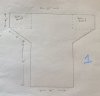
Here’s a concept drawing of #3 with platter and tonearms in relative position, the dotted lines represent the metal frame of the 412

646E0B20-868B-4C9E-B283-FB27CDD0E2FB.jpeg

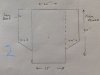
Next is a concept drawing of what the internal frame of #3 might look like, note that the intent is to attach an inner wood frame to the original metal frame.
7283F95A-B1BB-4197-9FCA-F76D44D9B6F5.jpeg

To determine what the concept will actually look like I’ll take some pine or plywood count to approximate size and lay it out, just to get a 3D vision of it.
 
Meant to post this earlier, something distracted me :confused:

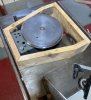
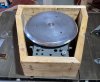
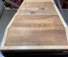
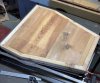
Anyway here’s the plinth mock-up out of scrap lumber; always good idea to do a model, found out I needed to add an inch or two to my depth in order to accommodate a 12” arm.

This only the outside frame, no internals and no top plate…..
931E1B65-214A-472B-BCE2-50C0C026C984.jpeg 6FEA90B2-B3BD-4661-A11B-54DDC5A72CC7.jpeg 5A648124-50C2-4B7C-9671-9205341D2406.jpeg 831AE438-EF86-41CB-9811-468CBE78E245.jpeg
 
  • Like
Reactions: T68
Looks good Andy. Even your mockups are nicely done. Getting those miters to fit tight is no trivial task. I don't think adding another 2" will mess with the proportions, that space will be filled with tonearms. They are always interesting to look at.
Are you fitting this with armboards? I'd want to be able to swap different arms in.

BillWojo
 
Looks good Andy. Even your mockups are nicely done. Getting those miters to fit tight is no trivial task. I don't think adding another 2" will mess with the proportions, that space will be filled with tonearms. They are always interesting to look at.
Are you fitting this with armboards? I'd want to be able to swap different arms in.

BillWojo

You hit the main point, insure the miters are correct, realize there are mathematical solutions to solve the angles but I’ve got to visualize the problem, yes it’s a flaw in my character and has to be mitigated ;) Next was just to just get a visual sense of how it will look.

My design concept includes 2 arm boards, revived the concept a bit after seeing the mock-up, but the 12” arm will go on the left and rest across the back with the 9” arm on the right.

I’ll add a couple of inches to the 2 short straight sections and see how it physically works out…..

Thanks,
Andy
 
Ok not much more done, had a slight accident :oops: having to work sorta one handed…

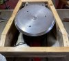
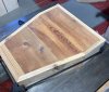
However did add 2 inches to the length and was able to stick the mock-up top plate into place.

The plinth will accommodate a 12 inch arm now and I’ll figure out the arm boards when the inner frame is in place.

The mock-up top plate will allow me to make the cut for the platter on test material, so if I make a mistake it won’t be the end of the world ;)

C373C94D-B78F-45AC-B125-588963E5557A.jpeg 6C21A02B-3601-4A54-AE4D-E229ACDF0A05.jpeg 04619F56-DB19-4598-9E82-0E77C5F7CAAE.jpeg 3693DC05-DAED-4E25-9BC7-D439D81D71F7.jpeg
 
  • Like
Reactions: T68
That looks pretty neat. 24 or 25 inch depth, do you have a deep enough shelf for it? My 2 arm Victor (JVC) has a plinth 22" wide and 20" deep. My shelf's are only 16" deep. I had a counter top place cut a piece of granite the same size to put on the shelf so I could put the Victor up there. Worked out well.
Any ideas yet as to the inside? Bit of a challenge with everything in the steel box.

BillWojo
 
You know Bill it’s a bit deceptive, the beauty of the design is that it’s only 20” deep, and if it were wider in the back it could be even shorter.

That’s also the danger in building a mock-up, one sees all the changes they’d like to make :confused:

The front miters are around 33 deg, exaggerate that a bit and reduce the depth even more….18 inches is probably very doable, and still look about the same.

Your solution for a 16 inch shelf is one I use for my Denon DP 75, it sits on a thick hardwood board that overhangs the shelf.

There’s going to be an inner frame tight against the metal frame, this will actually create cavities along the sides and under the arm boards, might add some jute or if constructed properly even sand or lead shot :)

Will bring it up just in its metal frame and test for extraneous noise, then go from there, you know the drill by now:thumbsup:

Edit: Keep in mind that this design is for 2 tonearms one of them 12 inches, if only one tonearm or even say 2, 9 inch arms were used it could be a much smaller footprint.

VR
Andy
 
20" deep isn't bad, looked deeper than that from the pics.
Well, now is the time to make changes before you commit to using some of your stash of fine wood. What were you contemplating?
The inner frame sounds like a great idea and should sink a lot of vibrations.
I have a belt drive TT here that is solid aluminum, the platter is 30 lbs alone. Total weight is 66 lbs. It's not something I care to move, it's a beast. When I set it up, I put the base in place and added the platter. So be careful with the lead. LOL
As far as arms go, I would definitely keep space for a 12" arm in the back. It's nice to have options.

BillWojo
 
20" deep isn't bad, looked deeper than that from the pics.
Well, now is the time to make changes before you commit to using some of your stash of fine wood. What were you contemplating?……

BillWojo


Was going to use this very special slab of Black Walnut I’d been saving :bye:

:rflmao:
 
Back
Top Bottom