• The move to the new server is done. There are some software and database maintenance updates in process. This has us passing the hat around to help out. We appreciate any donations. Seriously, even a dollar helps. The payment page may be found here - https://www.audiokarma.org/support.html

El34 / 12AX7 SE Build (My 1st build)

Thanks for all the input regarding grounding topology. I am following best I can but some of this is above my pay grade.

Update: Caps came in and I was able to finish the power side. Pot is here for the meter but I still need to finish that up. I plan on making sure the pot is set to maximum resistance before I power on for calibration.

I am having issues with the volume pot and now thinking I may forego one. I messed up the Alps pot by using one of those fancy pc boards thinking it would make things easier for hookup. I gave up messing with the board but broke a pin on the pot trying to remove it. Sooooo, I purchased one of those high dollar Audio Note pots but it measures weird. The sweep on one channel is 9 - 100 ohm and 3 - 95 on the other. But most concerning was at mid point, there was 9 ohm difference between the two channels. Seems like a balance issue to me. If I decide to not use a volume pot, I will make sure to modify the schematic with the proper resistor to maintain 100k input impedance.

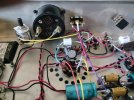
I may use the empty hole for a triode/ultra linear switch. Just need to figure out how to modify the schematic to do so. Here is and updated photo of the inside. I was proud of myself for the way I mounted the 500 ohm cathode resistors and have them directly under the chassis vent. Then I realized it would suck to service them in the future. Another 'oh well' moment. :confused:
Things are looking GREAT John!

Unless you spend mega buck$ on a really fancy stepped attenuator, potentiometers will always be a low tolerance beast (20% is common). The slight difference in overall end to end resistance, and resistance from wiper to one end is not really what counts, but the difference in output level between the two voltage dividers when in circuit. I have found that with even cheap pots the difference between the two levels left and right will not really be audible- take a step two feet to the left or right in your listening room, and you will have similar attenuation- our ears compensate very well for this. The pot is really only a convenience if you want to listen to a source directly without a pre-amp, as I will frequently do with a really good source to get the best accuracy. When not being used in this one mode, the volume pot is left all the way up (with volume being controlled on the source/preamp) and even a really cheap pot has no impact on circuit performance other than putting a 100K from the input to ground.

If you choose to leave the pot out, just leave it out- no substitution resistor needed. The input impedance is the resistance looking into the grid, parallel the 1M grid leak, so is already much higher than 100K, so much so that the additional 100K of the pot is really a don't care. Unless you are planning on a tube pre-amp that has a really high output impedance, most sources have well under 1K ohm output impedance, so can drive this amp without even noticing the load.

The 500 ohms- so you nixed bias adjustment?
 
Things are looking GREAT John!

Unless you spend mega buck$ on a really fancy stepped attenuator,
Just curious... can stepped attenuators be taper?
If you choose to leave the pot out, just leave it out- no substitution resistor needed. The input impedance is the resistance looking into the grid, parallel the 1M grid leak, so is already much higher than 100K, so much so that the additional 100K of the pot is really a don't care. Unless you are planning on a tube pre-amp that has a really high output impedance, most sources have well under 1K ohm output impedance, so can drive this amp without even noticing the load.
It is my understanding (Stephe) that the 1M would be replaced by the 100k. I will ponder this further.
The 500 ohms- so you nixed bias adjustment?
Yep. Keeping it simple (K.I.S.S.) on this one. With my experience and skill level I have decided to use the pots I ordred on my next build with fixed bias. Thinking of a 2A3, 6B4G or 300B.
 
Just curious... can stepped attenuators be taper?

It is my understanding (Stephe) that the 1M would be replaced by the 100k. I will ponder this further.

Yep. Keeping it simple (K.I.S.S.) on this one. With my experience and skill level I have decided to use the pots I ordred on my next build with fixed bias. Thinking of a 2A3, 6B4G or 300B.

From a technical standpoint (not market availability) a stepped attenuator can be linear or audio taper, but I expect that since they are primarily for volume control, that audio (logarithmic) taper would be most common. There are great explanations of logarithmic vs linear taper online so I won't repeat it here. For volume you want logarithmic, so the audio seems to increase in loudness correctly with volume knob position.

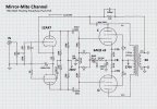
If Stephe advises replacing the 1M with the 100K that what you should do. The 1M input impedance (parallel the grid) is rather high, and could be prone to noise. When I do amplifier front ends, I typically use a 10K pot, used a 470K to ground, and put a 100kHz low pass filter between the pot and the grid to knock out stray RF and improve amplifier stability. An example is the Mirror-Mite 8W 6AQ5 push-pull that I am working on right now (sch for both floating paraphase and cathodyne versions below). I use 10k because at low volume I want to limit the source impedance seen by the grid, and most modern sources can drive 10K no problem. (You also see examples there of how I'm using those 50 ohm 2W wirewound pots for bias adjustment and current balancing.
 

Attachments

  • Mirror_Mite_Cathodyne_Schematic_Working.jpg
    Mirror_Mite_Cathodyne_Schematic_Working.jpg
    111.6 KB · Views: 12
  • Mirror_Mite_Floating_Paraphase_Schematic.jpg
    Mirror_Mite_Floating_Paraphase_Schematic.jpg
    120 KB · Views: 12
From a technical standpoint (not market availability) a stepped attenuator can be linear or audio taper, but I expect that since they are primarily for volume control, that audio (logarithmic) taper would be most common. There are great explanations of logarithmic vs linear taper online so I won't repeat it here. For volume you want logarithmic, so the audio seems to increase in loudness correctly with volume knob position.

If Stephe advises replacing the 1M with the 100K that what you should do. The 1M input impedance (parallel the grid) is rather high, and could be prone to noise. When I do amplifier front ends, I typically use a 10K pot, used a 470K to ground, and put a 100kHz low pass filter between the pot and the grid to knock out stray RF and improve amplifier stability. An example is the Mirror-Mite 8W 6AQ5 push-pull that I am working on right now (sch for both floating paraphase and cathodyne versions below). I use 10k because at low volume I want to limit the source impedance seen by the grid, and most modern sources can drive 10K no problem. (You also see examples there of how I'm using those 50 ohm 2W wirewound pots for bias adjustment and current balancing.
I decided to keep a volume pot and ordered a new Alps. It should measure better than the Audio Note one I have now.

I need to confirm my meter setup in parallel. To recap, the 0-1mA meter measured 41.4 ohms across the terminals. I replaced the faceplate with one from a 0-100mA unit. I have wired tapping between the cathodes and cathode resistors and ran to the L/R on the momentary switch. Then from the common on the switch to the 10 turn 100k pot (I made a custom bracket) and then from the wiper on the pot (bottom terminal in photo) to the (+) meter terminal. The (-) meter terminal wired to the star ground. To calibrate, I would measure the mA at the resistor using a multimeter then adjust the pot so the meter gets the same reading. Picture included for confirmation. Should this be good to go?

Meter Wiring.jpg
 
Looks excellent. Good work! To calibrate, you would measure voltage across the cathode resistor (should be around 31V), calculate current through the resistor (voltage/500 ohms) and dial the meter to that calculated current. It will only be as precise as your understanding of the actual resistance of the cathode resistors. (or more properly, since there are two perhaps slightly different resistors, the average of the two resistors.) You can measure the resistance with your best meter, then touch the meter probes together and subtract the lead-only resistance. That is about as accurate as you can be. Measuring the actual current through the cathode resistor is not possible without breaking the circuit and inserting an ammeter in place, which will change the cathode resistance (by adding a shunt in series) and will prevent an accurate measure.
 
Looks excellent. Good work! To calibrate, you would measure voltage across the cathode resistor (should be around 31V), calculate current through the resistor (voltage/500 ohms) and dial the meter to that calculated current. It will only be as precise as your understanding of the actual resistance of the cathode resistors. (or more properly, since there are two perhaps slightly different resistors, the average of the two resistors.) You can measure the resistance with your best meter, then touch the meter probes together and subtract the lead-only resistance. That is about as accurate as you can be. Measuring the actual current through the cathode resistor is not possible without breaking the circuit and inserting an ammeter in place, which will change the cathode resistance (by adding a shunt in series) and will prevent an accurate measure.
31 volts across a 500R resistor yields approximately 62mA which is probably a very accurate reading. I have been measuring voltage across resistors (to calculate current) for decades and it has always been accurate for design work.
 
Looks excellent. Good work! To calibrate, you would measure voltage across the cathode resistor (should be around 31V), calculate current through the resistor (voltage/500 ohms) and dial the meter to that calculated current. It will only be as precise as your understanding of the actual resistance of the cathode resistors. (or more properly, since there are two perhaps slightly different resistors, the average of the two resistors.) You can measure the resistance with your best meter, then touch the meter probes together and subtract the lead-only resistance. That is about as accurate as you can be. Measuring the actual current through the cathode resistor is not possible without breaking the circuit and inserting an ammeter in place, which will change the cathode resistance (by adding a shunt in series) and will prevent an accurate measure.
Thanks for the instructions. Pretty sure I can follow them!
How is the dim bulb tester? Are you using only one bulb, and what is it's wattage?
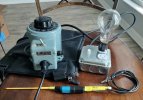
Got it done and I am using a 200 watt bulb. Here is a photo of my dim bulb, made in the USA variac and a home-made capacitor discharge tool:

Dim Bulb.jpg

To be honest, I am very nervouse about applying power. I didn't get a chance to test voltages of the power section due to waiting on parts before doing all the final wiring. I have been testing for shorts using the continuity beep feature on my multimeter. All seemed well but I was showing continuity on both the high voltage and 6.3v filiment leads to the star ground. This made sense to me because they both have center taps. The measured resistance on the high voltage was 38/41. But I couldn't get a reading on the 6.3v at all. In my mind, this could have a potential short? I still need to round up something for my 8 ohm load.
 
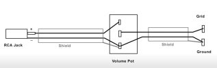
I am a little confused about the earth and signal ground connection. I thought that you were supposed to tie the RCA ground braid to the input tube ground point and not connect it to the RCA connection point (Leave it floating at the RCA end)

Can you clarify how you implement this properly?
This is what I am following when time to wire the volue pot:

Volume Pot Wiring.jpg
 
31 volts across a 500R resistor yields approximately 62mA which is probably a very accurate reading. I have been measuring voltage across resistors (to calculate current) for decades and it has always been accurate for design work.
Yep. I had measured the resistors prior to wiring and they measured 495/499 = 497 average. So I will average the measured voltage and calculate avg V/497 = mA.
 
Yep. I had measured the resistors prior to wiring and they measured 495/499 = 497 average. So I will average the measured voltage and calculate avg V/497 = mA.
If cathode voltage is 31v your 500Ω cathode resistors will be dissipating over 1.9w each. (.062 x .062 x500 = 1.92w) Resistors should be de-rated by a minimum factor of 3 and preferably higher. The schematic correctly shows them as 10w parts.

I can’t see a wattage rating written on them but the wattage spec of those type of resistors (finned gold metal body) assume that they are being screwed down to metal which acts as a heatsink and that thermal paste is used.

When mounted in free air their wattage rating drops significantly. If they are marked as 10w they’re probably ~2w or so as you have them mounted. They will run really hot and will likely fail.
 
Thanks for the instructions. Pretty sure I can follow them!

Got it done and I am using a 200 watt bulb. Here is a photo of my dim bulb, made in the USA variac and a home-made capacitor discharge tool:

To be honest, I am very nervous about applying power. I didn't get a chance to test voltages of the power section due to waiting on parts before doing all the final wiring. I have been testing for shorts using the continuity beep feature on my multimeter. All seemed well but I was showing continuity on both the high voltage and 6.3v filiment leads to the star ground. This made sense to me because they both have center taps. The measured resistance on the high voltage was 38/41. But I couldn't get a reading on the 6.3v at all. In my mind, this could have a potential short? I still need to round up something for my 8 ohm load.

Nice job on the power-up kit. During the decade that I was restoring antique radio, I came to detest using a variac alone, unless in conjunction with an ammeter, because if there was a short circuit, too much current could flow and do damage before you detected it. The main value of the variac was to be able to soak old electrolytics at a middling voltage to allow them to reform. I found the dim bulb tester to be a much more intuitive indication of how the device under test was functioning, and how it's current demand changed over time. I settled on an arrangement of using a 3-way bulb, that offered a 30-70-100W combination (that I discuss in power-on-preparation in a build thread). Using the rotary switch, I can start with the 30, which will glow brightly, then start to dim as the filaments warm up and the voltages will all be high enough to measure to confirm no shorts, but obviously low. Then I can "change gears" to the next higher, then highest filaments, accomplishing a similar task as the variac, but with more visual indication as I go. You will find that the 200W will probably either never glow, or if it does just faintly and for a short period. It will absorb the load helping to minimize damage if there is a short, but is a very low resistance, so I'm glad you are using it along with the variac.

The filament string will look like a short. You have a really thick low resistance winding parallel several filaments. You will have to carefully dial up the AC line voltage just a bit, and measure if you have AC voltage across the filaments- if you do, great, no short, and if you see also a voltage ascross the HV winding and DC voltage of any level at the capacitors, you are in good shape and you can proceed.
 
This is what I am following when time to wire the volume pot:

View attachment 3591315
I think that's fine. Since you have a ground wire tying the RCA connector common and the volume pot common together to only the input tube ground domain, it does not really matter if you connect both ends of the shield or not. The hum will be prevented because you used proper grounding- insulated the RCA connector from the chassis, so you are not allowing a ground loop that would tie chassis ground, and input tube ground together through the shield, so there is no pathway for current to flow through the shield if those two grounds have noise between them. Not connecting the shield at one end was typically a poor substitute for proper grounding.

You know, most people do not understand the purpose of the shield. In most people's imagination, the shield is somehow armor, preventing noise from penetrating the shield and getting to the center conductor. Actually the opposite is true- A coaxial arrangement with center conductor and outer shield are purposely capacitively coupled together, through the dielectric of the cable. At audio frequencies, the intent is that =every bit= of noise that is coupled into the shield is intentionally also coupled equally to the center conductor, such that the noise will be common to both conductors, and the receiver, which will respond only to the difference between the conductors, will reject the "common mode" noise. This strategy is most effective if you are using a true differential amplifier, but the principle is the same here.
 
When mounted in free air their wattage rating drops significantly. If they are marked as 10w they’re probably ~2w or so as you have them mounted. They will run really hot and will likely fail.

I would not change them immediately- while @FlaCharlie is completely right about rating, A 10W ceramic resistor is only a little bit longer than those, but it might be built to handle higher temperatures better than these metal resistors- whether they fail or not will come down to how these handle those higher temperatures. They probably will not fail right off the bat, but it is a long-term reliability concern. Get through power-on, and monitor them. Given your terminal strip assembly it will be really easy to replace them with bigger 10W ceramics later.
 
I would not change them immediately- while @FlaCharlie is completely right about rating, A 10W ceramic resistor is only a little bit longer than those, but it might be built to handle higher temperatures better than these metal resistors- whether they fail or not will come down to how these handle those higher temperatures. They probably will not fail right off the bat, but it is a long-term reliability concern. Get through power-on, and monitor them. Given your terminal strip assembly it will be really easy to replace them with bigger 10W ceramics later.
Well, they need to be replaced or, if they're rated for 10w, mounted correctly. So why wait? Roll the dice if you choose, though.
 
Another issue you may have when powering it up with a variac is that you’re using a 5AR4 rectifier, which is indirectly heated.

When you bring up the variac the 5AR4 won’t start to conduct / put out DC until you have the AC turned up quite a bit. Then it kicks in and DC voltages can be fairly significant. I forget the exact AC voltage but it might be ~70v or more.

When I bring up vintage gear that uses a 5AR4 on a variac I start with a 5Y3 rectifier and bring the voltage up very slowly, in steps of 10v. After several hours, when I get to maybe 70v, I switch to the 5AR4 and continue. Otherwise you won’t be able to check your various DC voltages for any red flags until they are relatively high. With the 5Y3 temporarily in place, you can identify any potential issues earlier and with less chance of damage if there is a problem.
 
Last edited:
Well, they need to be replaced or, if they're rated for 10w, mounted correctly. So why wait? Roll the dice if you choose, though.
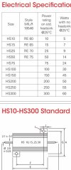
I am not much of a gambler. :) And I do appreciate bringing the potentional issue to my attention as it directs me to address things that I would never had thought about and thus learn new things. Indeed it is rated at 10 watts when mounted. However, the data sheet does rate it as 5 watts when not mounted to a chassis/heat sink. Not having the knowledge if 10 watts was an overkill for the circuit, is 5 watts sufficient? Either way, I would still do something to address the heat dissapation. I just don't want to have any screws showing on the top plate of the chassis, so an option may be mounting them to a finned heat sink? Another option is getting a higher rated one to get the 'free air' wattage up.
resistors.jpg
 
Last edited:
Another issue you may have when powering it up with a variac is that you’re using a 5AR4 rectifier, which is indirectly heated.

When you bring up the variac the 5AR4 won’t start to conduct / put out DC until you have the AC turned up quite a bit. Then it kicks in and DC voltages can be fairly significant. I forget the exact AC voltage but it might be ~70v or more.

When I bring up vintage gear that uses a 5AR4 on a variac I start with a 5Y3 rectifier and bring the voltage up very slowly, in steps of 10v. After several hours, when I get to maybe 70v, I switch to the 5AR4 and continue. Otherwise you won’t be able to check your various DC voltages for any red flags until they are relatively high. With the 5Y3 temporarily in place, you can identify any potential issues earlier and with less chance of damage if there is a problem.
I do have a 5V4G. Would that be suitable for a safer startup?
 
I am not much of a gambler. :) And I do appreciate bringing the potentional issue to my attention as it directs me to address things that I would never had thought about and thus learn new things. Indeed it is rated at 10 watts when mounted. However, the data sheet does rate it as 5 watts when not mounted to a chassis/heat sink. Not having the knowledge if 10 watts was an overkill for the circuit, is 5 watts sufficient? Either way, I would still do something to address the heat dissapation. I just don't want to have any screws showing on the top plate of the chassis, so an option may be mounting them to a finned heat sink? Another option is getting a higher rated one to get the 'free air' wattage up.

View attachment 3591499

About 2 Watts are being dissipated in each resistor at normal bias currents. 5W is safe "reliability" overkill for this, 10W was chosen as "gonzo" performance overkill because a resistor that is not being overly taxed will be more stable as the temperature is not swinging so much. This is why I suggested the resistors as mounted will be fine for power up and initial testing. I did not want you to have to delay power on to place another order.

Just stick with the 5AR4. With even a tiny bit of AC voltage you will be able to tell if the HV and filament secondaries are showing some signs of life, then =some= DC voltage will be present at the caps and confirm there is not a short there. Take some measurements, dial it up a bit more, rinse and repeat. No need to sit for hours. It's not an antique radio waiting for electrolytics to reform- it's either shorted, or not.
 
Back
Top Bottom