• The move to the new server is done. There are some software and database maintenance updates in process. This has us passing the hat around to help out. We appreciate any donations. Seriously, even a dollar helps. The payment page may be found here - https://www.audiokarma.org/support.html

El34 / 12AX7 SE Build (My 1st build)

About 2 Watts are being dissipated in each resistor at normal bias currents. 5W is safe "reliability" overkill for this, 10W was chosen as "gonzo" performance overkill because a resistor that is not being overly taxed will be more stable as the temperature is not swinging so much. This is why I suggested the resistors as mounted will be fine for power up and initial testing. I did not want you to have to delay power on to place another order.
Neat. But for future reference, going "gonzo" would also mean the resistor would run cooler?
it's either shorted, or not.
Please Lord, let it be "not". :angel:
 
I do have a 5V4G. Would that be suitable for a safer startup?
No, the 5V4G is also indirectly heated, which means that it has a cathode. The reason the 5Y3 works is because it’s directly heated. This is not a huge deal, and you don’t need to power it up super slowly because all your caps are new.

Just don’t think that something is wrong when you crank the AC on the variac up quite a way and your DC voltage is still really low. It’s just not as much of a linear progression as you would see with a 5Y3.

Also, a 200w bulb is not ideal for use in a dim bulb tester. When I first started I didn’t have a variac. I used a dim bulb tester and powered up using a series of bulb wattages: 7.5w, 15w, 25w, 40w, 60w, 75w and finally 100w. Incandescents are hard to find these days, though. But if you can find a lower wattage that would be better.

the data sheet does rate it as 5 watts when not mounted to a chassis/heat sink. Not having the knowledge if 10 watts was an overkill for the circuit, is 5 watts sufficient?
If the spec sheet on the resistors says 5w when mounted in free air I would call that OK-ish since it’s roughly 2.6x dissipation but I prefer to de-rate more if possible. Using a heat sink or a regular 10w rated wirewound is more conservative and potentially more reliable in the long run.
 
Neat. But for future reference, going "gonzo" would also mean the resistor would run cooler?
Yes, in general. Manufacturers generally indicate that a resistor can handle up to it's rated power, for at least as long as it takes for your warranty to expire. We have all replaced resistors that the manufacturer has chosen, that have become charcoal, or have left darkened PCB because they run too hot, so experience leads us to be conservative. The standard rule is to go with a wattage that is at least 2X the actual power expected in the resistor, and in certain cases, for those expecting to dissipate a lot, or for performance reasons, far over that required. It is wise to calculate the power being dissipated in each resistor and confirm you are using the right value. Some resistors achieve their power rating because they are physically big so they can radiate and convect more heat, (or through contact with a surface like the metal ones) and some get a power rating based upon their ability to withstand super high temperatures, like the ceramic/cement type. A larger resistor will run cooler, because it can dissipate the less than spec heat being generated within it more effectively, so the temperature stays below it's rating. This will make the resistor last longer, and for the case of cathode resistors, the resistance value will remain more constant because the temperature does not reach such extreme level.

 
Yes, in general. Manufacturers generally indicate that a resistor can handle up to it's rated power, for at least as long as it takes for your warranty to expire. We have all replaced resistors that the manufacturer has chosen, that have become charcoal, or have left darkened PCB because they run too hot, so experience leads us to be conservative. The standard rule is to go with a wattage that is at least 2X the actual power expected in the resistor, and in certain cases, for those expecting to dissipate a lot, or for performance reasons, far over that required. It is wise to calculate the power being dissipated in each resistor and confirm you are using the right value. Some resistors achieve their power rating because they are physically big so they can radiate and convect more heat, (or through contact with a surface like the metal ones) and some get a power rating based upon their ability to withstand super high temperatures, like the ceramic/cement type. A larger resistor will run cooler, because it can dissipate the less than spec heat being generated within it more effectively, so the temperature stays below it's rating. This will make the resistor last longer, and for the case of cathode resistors, the resistance value will remain more constant because the temperature does not reach such extreme level.
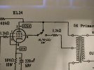
Thanks, that all makes sense. Now for another question if you don't mind. IF I decide to add a UL/Triode switch, is it this simple or will I need to add some resistance on the triode side of the sw and if so, what would be the value?

UL Triode Switch.jpg
 
Thanks, that all makes sense. Now for another question if you don't mind. IF I decide to add a UL/Triode switch, is it this simple or will I need to add some resistance on the triode side of the sw and if so, what would be the value?
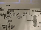
I would do it like this shown below, lower the 1.2K to 1.1 K and put a 100R next to the tube. Also if you plan to do this, I would add a center off DPDT switch for the feedback resistor, to be able to switch in a higher value resister (maybe 750k?) and/or remove it entirely when in triode mode. If you don't adjust that feedback resistor, which does impact the tone of the amp, it's gonna sound VERY dull and lifeless in triode mode.

UL Triode Switch Edit.jpg
 
From a technical standpoint (not market availability) a stepped attenuator can be linear or audio taper, but I expect that since they are primarily for volume control, that audio (logarithmic) taper would be most common. There are great explanations of logarithmic vs linear taper online so I won't repeat it here. For volume you want logarithmic, so the audio seems to increase in loudness correctly with volume knob position.

If Stephe advises replacing the 1M with the 100K that what you should do. The 1M input impedance (parallel the grid) is rather high, and could be prone to noise. When I do amplifier front ends, I typically use a 10K pot, used a 470K to ground, and put a 100kHz low pass filter between the pot and the grid to knock out stray RF and improve amplifier stability. An example is the Mirror-Mite 8W 6AQ5 push-pull that I am working on right now (sch for both floating paraphase and cathodyne versions below). I use 10k because at low volume I want to limit the source impedance seen by the grid, and most modern sources can drive 10K no problem. (You also see examples there of how I'm using those 50 ohm 2W wirewound pots for bias adjustment and current balancing.
The 1 meg is there simply there in case the wiper on the pot goes open the input tube grid still has a reference to ground. And while "modern sources" can drive a 10K load, some tube based sources, like my phono stage don't sound great being loaded that low. If I remove the volume pot, I replace the 1 meg with something around 100k - 220k to have a more "normal" input impedance.
 
Last edited:
I would do it like this shown below, lower the 1.2K to 1.1 K and put a 100R next to the tube. Also if you plan to do this, I would add a center off DPDT switch for the feedback resistor, to be able to switch in a higher value resister (maybe 750k?) and/or remove it entirely when in triode mode. If you don't adjust that feedback resistor, which does impact the tone of the amp, it's gonna sound VERY dull and lifeless in triode mode.
Well Stephe, you are forcing me to use my one remaining brain cell to learn. :) Is this a possible solution to use one switch and keep proper feedback for the UL/Triode modes?
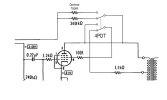
Triode UL Modification.jpg
 
Okay, did my first power up. I disconnect the star grounds for the input and driver tubes so just to test that all is okay with the power supply. I have a problem. The B+ voltage is thru the roof at 501V. I used the dual choke scheme from Skunkie's EL34/6SQ7 project that called for a B+ of 410V. This EL34/12AX7 that I am doing calls for a B+ of 430V. I thought it would be close enough but did use psud2 software using the exact specifications of my parts and it indicated I should achieve a B+ of 431V. It all should have worked out.

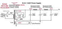
I measured all the points of the power schematic and was totally surprised at the voltage coming direct from the power transformer. See my measurements below:

Power Supply Problem.jpg
The power transformer appears way out of spec. I don't know if it was bad from Hammond or if me potting it had some adverse effect. But I did put the actual readings back into psud2 and I should be getting a B+ at C3 of 461V. Not sure how to proceed. Going to the single choke scheme won't solve the excessive voltage from the PT.

I am in a holding pattern now. :( And I am still bummed that there was no Monday Monologue this week. ;)
 
Last edited:
That's what happens when you run a tube power supply without any loading. The power transformer will have resistive, inductive, and magnetic losses, and there will be a voltage drop through the rectifier when there is a load current flowing, so the voltages will pull down to the correct levels when they are loaded. Reconnect your grounds, and try with the proper loads. At least you verified nothing is shorted.

Also be sure to measure your input line voltage for reference.
 
That's what happens when you run a tube power supply without any loading. The power transformer will have resistive, inductive, and magnetic losses, and there will be a voltage drop through the rectifier when there is a load current flowing, so the voltages will pull down to the correct levels when they are loaded. Reconnect your grounds, and try with the proper loads. At least you verified nothing is shorted.
But how can Hammond give a 383V spec. if they don't know how much load will actually be appled? A 30V difference seems like alot. But hey, I am new and what do I know? :) Don't get me wrong. If all if this is normal the I am a happy camper!
Also be sure to measure your input line voltage for reference.
I did. Made sure it was dead nuts on 120v coming in the IEC port.
 
Reconnect your grounds, and try with the proper loads. At least you verified nothing is shorted.
I don't have the single/volume pot wiring done yet. Can I safely put all the tubes in and test without a signal and speakers? I don't want to kill any transformers, etc.
 
I don't have the single/volume pot wiring done yet. Can I safely put all the tubes in and test without a signal and speakers? I don't want to kill any transformers, etc.
Conventional wisdom is you need a load on the speaker connections for a tube amp to power it up, either speakers or dummy load (like this https://www.amazon.com/dp/B07QV3S2F5?ref_=ppx_hzsearch_conn_dt_b_fed_asin_title_1).

You probably talked about this earlier in the thread, but that is not the power transformer specified in Skunkie's schematic. https://www.skunkiedesigns.com/6sq7?pgid=kv1sk1f9-15d559e2-4779-495c-b486-9cade61792dc
 
But how can Hammond give a 383V spec. if they don't know how much load will actually be appled? A 30V difference seems like alot. But hey, I am new and what do I know? :) Don't get me wrong. If all if this is normal the I am a happy camper!

I did. Made sure it was dead nuts on 120v coming in the IEC port.

Transformer specs are typically given for @ rated load. The sag on a transformer secondary is specified as a percent of regulation, meaning that for a given industry standard regulation spec (I think 5% for some, 9% for others) that the unloaded voltage will have sagged by that percent at the rated load current (assuming all secondaries are at the rated load).

I don't have the single/volume pot wiring done yet. Can I safely put all the tubes in and test without a signal and speakers? I don't want to kill any transformers, etc.

I'm not sure what your exact connectivity is yet- But I would make sure there is a resistance to ground on the grids, even if just the 1 meg grid return, and no other input signal is fine. If you don't have a dummy load to load the outputs (or an o-scope to monitor the outputs) then I would connect up some "cheap, it's OK if they blow up" speakers so you can monitor if you have hum, oscillation, etc. I don't recommend running unloaded unless you are certain the amp is stable in that configuration. Since you are not running any signal through yet, you can just throw any 4-8 ohm resistor across the outputs for just testing. (but then you can't hear what the output is doing)
 
Conventional wisdom is you need a load on the speaker connections for a tube amp to power it up, either speakers or dummy load (like this https://www.amazon.com/dp/B07QV3S2F5?ref_=ppx_hzsearch_conn_dt_b_fed_asin_title_1).
TY
You probably talked about this earlier in the thread, but that is not the power transformer specified in Skunkie's schematic. https://www.skunkiedesigns.com/6sq7?pgid=kv1sk1f9-15d559e2-4779-495c-b486-9cade61792dc
It is actually the alternative power supply: https://www.skunkiedesigns.com/6sq7?pgid=kv1sk1f9-58aefa56-6cf7-41b3-9ff3-af0ea08c7179
But Stephe gave it a thumbs up for this build.
 
The 1 meg is there simply there in case the wiper on the pot goes open the input tube grid still has a reference to ground.
Yes- I learned that from you. Wise lesson.

And while "modern sources" can drive a 10K load, some tube based sources, like my phono stage don't sound great being loaded that low. If I remove the volume pot, I replace the 1 meg with something around 100k - 220k to have a more "normal" input impedance.

I assume you are referring to the EAR834 clone with the 12AX7 based cathode follower output? When I made reference to modern sources, it was sort of short-hand for "just about everything except high-impedance tube-based sources that are relatively rare these days", and the EAR834 is certainly that. It is a terrific design, and I would really like to build one, so thank you for doing your videos on that design. What I mean is that these days, people are intermixing tube and solid state components in experimenting with sound, and our job as engineers/builders is to provide designs that can intermix robustly as much as possible in the current environment. As long as one is aware that the EAR834 is boutique and requires a high input impedance, no problem. Not every amplifier is going to accommodate this one type of source, which is a shame. When I build it I would probably tweak the output stage to provide a lower output impedance so it would be more interchangeable. I know this might change the uber "awesome sauce" sound that this has, but maybe not as much as an impedance mismatch to my favorite power amp.

One issue I did want to ask about, and I'm sure you probably have addressed it- With the miller capacitance and high gain of the input 12AX7 for this EL34 SEUL amp, I understand you have to be careful about how much series resistance you have between the source and the grid- For the 100K fixed to ground that is no problem. But with the 100K volume control, it seems you could risk at lower volume setting having a high frequency roll-off because of the higher series source resistance. I should model the problem and discover for myself whether 100K would risk making an audible difference, I suspect it's probably towards the high end of resistance without too much impact. I suspect you use this pot so your amps can use the EAR834? Otherwise, for almost any other source 10K is a great input impedance- If avoids the HF roll-off, has good noise rejection and still 10X or more of the common source output impedance.


1757455267715.png
 
Last edited:
Transformer specs are typically given for @ rated load. The sag on a transformer secondary is specified as a percent of regulation, meaning that for a given industry standard regulation spec (I think 5% for some, 9% for others) that the unloaded voltage will have sagged by that percent at the rated load current (assuming all secondaries are at the rated load).
Thank you. I am learning a bunch.
I'm not sure what your exact connectivity is yet- But I would make sure there is a resistance to ground on the grids, even if just the 1 meg grid return, and no other input signal is fine. If you don't have a dummy load to load the outputs (or an o-scope to monitor the outputs) then I would connect up some "cheap, it's OK if they blow up" speakers so you can monitor if you have hum, oscillation, etc. I don't recommend running unloaded unless you are certain the amp is stable in that configuration. Since you are not running any signal through yet, you can just throw any 4-8 ohm resistor across the outputs for just testing. (but then you can't hear what the output is doing)
I am going ahead and temporarily wire in signal wires from the rca jacks to the input tube as if there is no volume pot. I won't bother with the shielding and not worried about impedence at this stage. I will find some loading for the speaker jacks. Will that do for now?
 
Thank you. I am learning a bunch.

I am going ahead and temporarily wire in signal wires from the rca jacks to the input tube as if there is no volume pot. I won't bother with the shielding and not worried about impedence at this stage. I will find some loading for the speaker jacks. Will that do for now?
Do you have the 1M or 100K from grids to ground? This is a must no matter what else.

Yes, but keep in mind with "long" unshielded wire going to the input grids, it may serve as an antenna to couple in more noise, and if this design is marginal in stability already?, may cause oscillation. Just keep them short, (twist them at least) and away from the outputs and it should be fine. You could just leave no input signal (with grids grounded through 100K/1M, etc) , and monitor the outputs to achieve power on, and take voltages, and leave the "victory lap audio listen" until you get your inputs connected up properly.
 
Do you have the 1M or 100K from grids to ground? This is a must no matter what else.
The 1M is already wired in at this point. Just lacking the pot and signal wires from the rca jacks.
You could just leave no input signal (with grids grounded through 100K/1M, etc) , and monitor the outputs to achieve power on, and take voltages, and leave the "victory lap audio listen" until you get your inputs connected up properly.
Not sure what you mean by "monitor the outputs"? And if I understand correctly, no need to wire in the signal wires if the 1M is wired between grid and ground?
 
One thing you always have to do during power-up is to detect if there is a loud buzz, hum, motor-boating, oscillation, etc, to make sure that the output transformers (or your speakers) will not be damaged by a connection error. Ideally, you use an O-scope to watch the loaded output signal because oscillation can be far above audible frequencies (100kHz+). If you don't have this, at least use cheap speakers so you can have audible indication of a problem. You should hear very little if any hum and no other strange noises.
 
Back
Top Bottom