• The move to the new server is done. There are some software and database maintenance updates in process. This has us passing the hat around to help out. We appreciate any donations. Seriously, even a dollar helps. The payment page may be found here - https://www.audiokarma.org/support.html

El34 / 12AX7 SE Build (My 1st build)

And if I understand correctly, no need to wire in the signal wires if the 1M is wired between grid and ground?

For power on, you are just trying to determine that all of your voltages looks ballpark correct, and nothing smokes. For that, you don't need an audio signal, but the grids DO need a path to ground so they are properly biased.
 
Very nice. Great job!

On mine I added some connectors so I can just plug a cable in for the oscilloscope. Clip leads work fine too at these frequencies.

Do you have an oscilloscope to watch the outputs and do some characterization? Before I got my scope I just used some sacrificial lamb thrift-store speakers as power-on fodder.
 
Very nice. Great job!
Thanks!
Do you have an oscilloscope to watch the outputs and do some characterization?
No scope. No knowledge of how to use one, BUT, a friend in the local audiophile club has offered to test it with his equipment. He may also download the Audio Anylizer software and learn to use it like Skunkie uses. That would be cool beans.

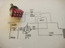
On another note, while I have been waiting on parts, I have been pondering more about the volume pot. I am really leaning towards not having one and use the hole in the future for the triode/UL switch. With the McIntosh preamp I use, I see no need really for the pot and it would just be something just getting in the way of the signal path. The triode/ul switch is going to get crowded. LOL

Triode UL Switch.jpg
 
Last edited:
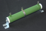
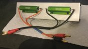
Something else to keep on hand when powering up the power supply for the first time is an adjustable power resistor (100W~200W). For a 450VDC supply, 3kOhm is good. This will allow you to provide a load for the power supply and ensure your main B+ voltage is correct or close to where it needs to be before it is decoupled by the other power supply sections. Adjust the resistor to various positions to draw alternate currents.

100W is the minimum I recommend because it will get hot, but will allow plenty of time to check voltages and then turn off the power supply.
 

Attachments

  • Adjustable Power Resistor_Example.png
    Adjustable Power Resistor_Example.png
    525.8 KB · Views: 4
Did my first power-on with all tubes in place, dummy load but no input signal. No hum/whine or weird noises. Dead quiet. Measured voltages after about 20 minutes of warm-up. I have one spot that should be measuring 210V but I am getting a reading of 417V. Obviously I must have messed something up. Here are all the readings:

Startup Voltages.jpg
 
Have you double checked the values of the installed 360k and 240k ohm resistors on either side of where it is suppose to read 210V? I've goofed up and installed resistors that were an off by a few zeros.
 
Have you double checked the values of the installed 360k and 240k ohm resistors on either side of where it is suppose to read 210V? I've goofed up and installed resistors that were an off by a few zeros.
Bingo! I had a 360 instead of a 360k ohm shade resistor. I snipped it and got a reading of 195V. I patched in a 300k I had and it reads 233V. So a proper 360k should make it right. Now back to ordering and take a break. I am also now reading a proper 1.8V at the 12AX7 cathode. Hopefully the other voltages are workable. Once I get the proper 360k installed, I will post new readings.

THANK YOU SIR! I love AK.
 
Last edited:
I think it's time to switch to speakers. Now that you have found the mix-up, I think it's safe to try some audio with your good speakers. Hate to see that put off for another parts order. I was going to suggest that you probably want to complete the input wiring and wring out the design before you start adding the UL/triode complication.

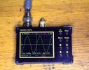
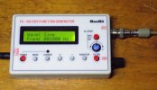
Unless this is a one and done build and you are not interested in learning, it might be time to invest in some thrift store speakers for power-on, and picking up a cheap O-scope and signal generator. Most people are quite surprised at just how cheap but powerful they have gotten. My starter scope and signal generator were each around $30, and there are much better for under $100. Even with these cheapies, you can do a full set of characterization, everything except perhaps distortion measurement, and I do a good walk through of what you need and how to do the basics in a build thread.

@THD+N 's suggestion about the adjustable power resistor is a very good one- but most useful if you are doing custom designs with unknown transformers, so I'm definitely picking one up.

We all look forward with baited breath to hear how your amp sounds. I would think you would be chomping at the bit!


1757701165521.jpeg 1757701182207.jpeg
 
Bingo! I had a 360 instead of a 360k ohm shade resistor. I snipped it and got a reading of 195V. I patched in a 300k I had and it reads 233V. So a proper 360k should make it right. Now back to ordering and take a break. I am also now reading a proper 1.8V at the 12AX7 cathode. Hopefully the other voltages are workable. Once I get the proper 360k installed, I will post new readings.

THANK YOU SIR! I love AK.
Glad to help.
 
I think it's time to switch to speakers. Now that you have found the mix-up, I think it's safe to try some audio with your good speakers. Hate to see that put off for another parts order. I was going to suggest that you probably want to complete the input wiring and wring out the design before you start adding the UL/triode complication.
Got the input wiring done. Super simple since there is no pot now! I don't plan on addressing the UL/Triode issue for some time. I did get a bad switch however for the meter. I will have a new one along with proper resistors on Sunday. I want to get it all sorted before putting it in my system. And for some reason I can't measure the bias mA using my multimeter to calibrate my chassis meter. It is DC ma, right? The chassis meter seems to be working fine and will be the cat's meow once dialed in.
Unless this is a one and done build and you are not interested in learning, it might be time to invest in some thrift store speakers for power-on, and picking up a cheap O-scope and signal generator. Most people are quite surprised at just how cheap but powerful they have gotten. My starter scope and signal generator were each around $30, and there are much better for under $100. Even with these cheapies, you can do a full set of characterization, everything except perhaps distortion measurement, and I do a good walk through of what you need and how to do the basics in a build thread.
Will be looking for the test equipment especially since I want to do another build in the near future. Possibly based on Skunkie's KT120 circuit except instead of monoblocks, a single chassis. I am hunting parts and learning how to design a proper power circuit. Possibly a dual rail. The scope and signal generator you showed are really compact. I like that!
We all look forward with baited breath to hear how your amp sounds. I would think you would be chomping at the bit!
Yes I am but don't want to rush and introduce anymore issues. It is kinda like sky diving for the first time. Did I pack the shute correctly? o_O
Thank you for all your support.
 
I will have a new one along with proper resistors on Sunday. I want to get it all sorted before putting it in my system.
Your choice. Most folks do something to listen to the amp (and dial it in, correct any mistakes, etc) before buttoning it up and putting it on expensive speakers. I would never connect any amp to expensive speakers until it passes the "thrift store speakers in the garage" test.

And for some reason I can't measure the bias mA using my multimeter to calibrate my chassis meter. It is DC ma, right? The chassis meter seems to be working fine and will be the cat's meow once dialed in.
Are you breaking the cathode circuit to place your ammeter in series to measure current? As I said before, this is not advised. Your multimeter ammeter will place a shunt resistor of unknown value in series with the cathode and will cause the cathode current to change. The cathode current is correct for the 500 ohm only being in circuit. This is why I detailed that you must measure the voltage across the 500 ohms, calculate current (I = V/R) and dial the meter in to that calculated current.

Yes I am but don't want to rush and introduce anymore issues. It is kinda like sky diving for the first time. Did I pack the shute correctly? o_O
Thank you for all your support.
And that is exactly why you prove the circuit works with cheap speakers first.
 
Your choice. Most folks do something to listen to the amp (and dial it in, correct any mistakes, etc) before buttoning it up and putting it on expensive speakers. I would never connect any amp to expensive speakers until it passes the "thrift store speakers in the garage" test.
I will get to the thrift shop tomorrow.
Are you breaking the cathode circuit to place your ammeter in series to measure current? As I said before, this is not advised. Your multimeter ammeter will place a shunt resistor of unknown value in series with the cathode and will cause the cathode current to change. The cathode current is correct for the 500 ohm only being in circuit. This is why I detailed that you must measure the voltage across the 500 ohms, calculate current (I = V/R) and dial the meter in to that calculated current.
I had forgotten your earlier post. I did the calc and running at 60mA. Meter now reads great.
And that is exactly why you prove the circuit works with cheap speakers first.
Agreed. Still learning the basic steps.
 
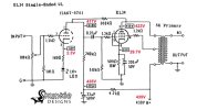
Well, things are going well. Below are the voltage readings and a video link to the power-on using $10 Goodwill speakers and a $23 Bluetooth audio adapter. I will button it up, put in the good tubes and hook-up in my main system for critical listening. Any comments or suggestions are welcome.

Final schematic and voltages.jpg

 
I don't think it really matters, but when I used that larger power transformer with the 6SQ& build, I used a 5V4G rectifier, which would lover the B+ just a breath and match the posted schematic's numbers.
 
Congratulations in a successful build!!
Thank you!
I don't think it really matters, but when I used that larger power transformer with the 6SQ& build, I used a 5V4G rectifier, which would lover the B+ just a breath and match the posted schematic's numbers.
You are correct. I happened to have a NIB 1945 JAN CHS 5V4G and it brought the B+ down to 434. I will rock with it and besides, I really like the Coke bottle look. Thanks Stephe for all your help and support!
 
You are correct. I happened to have a NIB 1945 JAN CHS 5V4G and it brought the B+ down to 434. I will rock with it and besides, I really like the Coke bottle look. Thanks Stephe for all your help and support!
Yeah, they do look cool and are much easier to source NOS. And I agree, nice looking build! hope you like the way it sounds.
 
Yes! Congratulations! A superior looking amp- very classy, especially for a first build!

Looking forward to more updates as or if you do further upgrades. Also interested in any characterization or testing you do. I would love to see the 10kHz square wave response, output impedance, and frequency bandwidth, but I'm a geek. Before you leave for awhile, you should post a final round of pictures, and maybe add them to an album in the "media" area. She's a looker.
 
Yes! Congratulations! A superior looking amp- very classy, especially for a first build!

Looking forward to more updates as or if you do further upgrades. Also interested in any characterization or testing you do. I would love to see the 10kHz square wave response, output impedance, and frequency bandwidth, but I'm a geek. Before you leave for awhile, you should post a final round of pictures, and maybe add them to an album in the "media" area. She's a looker.
Thank you Mr. Parks.

I am pursuing getting this on a scope and will post the results.

And a special thanks to you for all the suggestions and solutions to my issues! The bias pots I know are a good idea but I really didn't want to get ahead of my current skill level. However, my confidence is up and looking forward to another build. I will get some beauty shots and post them. Thanks again.
 
Last edited:
Back
Top Bottom