

You are using an out of date browser. It may not display this or other websites correctly.
You should upgrade or use an alternative browser.
You should upgrade or use an alternative browser.
Fisher 480A Cap Questions
- Thread starter relaximus
- Start date
Register to hide this ad


skykng
Member
Your chassis is nice and clean. As Kvflyer and Coman61 say above, the three cylindrical "cans" are the filters. The amp is filtered well. You also have a cardboard covered can under theOkay, I'm getting some hum from my Fisher Electra console. I'm just guessing that this may be due to bad filter caps. Could someone please tell me, from the below pics, just where these are?


Thanks!
Dave
chassis in the separate tuner section that you'll need to change someday to finish this job. You can read the values of the capacitor sections inside the cans on the side the of the cans. Order replacements for those values - voltages can be higher (450vdc is OK for the 250vdc). You don't want to remove the cans from the chassis -- we'll work under the chassis to install the news ones. The new caps (called electrolytic capacitors) are smaller than the old ones and will fit OK under the chassis. EG: Looking at the btm picture, the two at the top look the same (but they are not). The one on the upper left is two 40mfd @ 450vdc and a 100mfd @ 250vdc built into the one can. Notice on the side of the can that there is a symbol next to each value - now look at the bottom of the can, and you'll see that symbol where the pin enters the can. There is a triangle, a semicircle, and a square --each representing one of the values above. Pretend the upper left terminal on the can is the triangle, it has an orange wire and the 1 watt 3300 ohm resistor going to it - and pretend the triangle stands for one of the 40mfd @450vdc sections of the can. What we're going to do is remove or cut that orange wire and the end of the resistor from that terminal marked with the triangle. Make notes as you go. Do the same at the other terminals - noting the values of the caps - second terminal has the blue wire and the other end of the resistor, say it is the square, etc......Then with all the wires and the resistor moved out of the way, take a pair of pliers and twist back and forth on the terminals of the can to break them off at the base of the can. Because that can and the one next to it are grounded to the chassis, just wire the new cap (of the same value) by attaching the orange wire and the resistor end onto the positive end of the cap right where the bare wire comes out of the black end -- and solder the connection. Cut off excess bare wire from the positive end. If you want to, you can get some black insulating goop at Walmart auto section to brush onto the bare end of the cap to cover it with a little insulation. Now the metal end of the cap is free and has a bare wire coming out of it.
Just wait for now to solder that to ground on the chassis. Do the same thing to the other wires and resistor end -- attaching them to the new caps and soldering them. Now you have three new caps with the positve ends wired according to your notes and the ground ends free. Verify by your pictures you have it right. Now we just need to fit the caps into the available space - filter caps do not get hot. Because you have two other cans to replace, you want to focus on the empty space to the left of and on top of the can you are replacing -- that's why we broke off the old pins on the can. With me so far?? Let me know and we'll continue..........
good luck, steve ps: you can do this.

relaximus
Consoles 'Я' Us
skykng:
Well Steve, all I can say is thank you so much. I think you've given me the courage to go ahead and try this. I'll grab the cap values tonight and order them tomorrow. Please don't go anywhere for a while, I'm gonna need ya to see me through this!
Did you re-cap your 460-A yet? If so, do you have any before/after pics?
BTW: Where in VA are you? I grew up in Lynchburg and went to school in Charlottesville (UVa).
Best regards,
Dave
Well Steve, all I can say is thank you so much. I think you've given me the courage to go ahead and try this. I'll grab the cap values tonight and order them tomorrow. Please don't go anywhere for a while, I'm gonna need ya to see me through this!
Did you re-cap your 460-A yet? If so, do you have any before/after pics?
BTW: Where in VA are you? I grew up in Lynchburg and went to school in Charlottesville (UVa).
Best regards,
Dave

coman61
Well-Known Member
Dave, here is some good reading. Here you can see exactly what skykng is talking about.
http://antiqueradio.org/recap.htm
http://antiqueradio.org/recap.htm
skykng
Member
OK Dave: Good jack hack point about the voltages!! I assumed (bad word) the originial caps were discharged. Capacitors store electricity - that's their function - so if you power up your amplifier, those can capacitors can have up to 400 volts stored in them. If the amp is on the bench and has not been powered in a while, they are safe, BUT just to be sure, take a screwdriver with
an insulated handle and touch each of those contacts at the base of the can caps to ground. Or - use an alligator clip jumper wire, connect one clip to the chassis and the other to the screwdriver and touch each terminal. To see the danger, power it up, then unplug it, and touch each terminal to ground -- you will see a big spark as it grounds out. Key though, is to work with a discharged chassis --nowhere near being powered up. JHack is right on --
those voltages can kill you! Be safe and sure.
Now--Do you have a schematic for the amp?
I did recap the filters in my 460A, and I thought of you by
taking some picures. But I cannot figure out how to put arrows on the photo or how to mark the photo somehow to point out what I talk about. So - you'll just have to read the values on the replacement caps as we go. Another thought, my amp is not going to the Pebble Beach concours d'elegance competition, so it is not pretty or perfect. Perfect is the enemy of good enough. I am a functional fella. Also - remember this - resistors in series add, and capacitors in parallel add. Eg: two 47mfd 450v caps wired in parallel equal 94mfd @ 450vdc = close enough to 100mfd used in the 460A. Another Eg: a 47mfd 450vdc cap wired in parallel with a 10mfd @ 450vdc = 57 mfd @ 450vdc - close enough to the 60 mfd used in the 460A. I have these caps in my parts bin -- when you order, you'll get one cap say at 100mfd, so you don't have to wire two of them in parallel. But if you know the rule, it may come in handy in the future. So my replacement caps are two caps wired in parallel to give me the necessary values. Notice that the can with the cardboard cover has the case or shell of the cap NOT grounded to the chassis. The upper two caps do ground to the chassis. The cardboard covered cap is a 100mfd @250vdc and the negative side is connected to the red/yellow wire coming out of the transformer ( high voltage secondary) - the positive side is connected to the red wire that is the other end of the secondary high voltage winding.
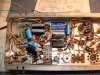
The first picture shows that I have wired in the two black colored 47mfd caps with the resistor across both positive ends. Those two are for the 40mfd in the top left cap that ground to the chassis. By the way, you must have a newer version of the amp because your wiring is a little different than mine. My dropping resistor is 2200 ohms and yours is 3300 ohms. Your layout of the green 220 ohm resistors is different than mine and your rectifier diodes are different also. You said you didn't know a rectifier from a capacitor -- now you will! The rectifier diodes in yours are the two little cylindrical shiny metal doodads that are connected to the red wire coming out of the transformer. The upper one goes directly to the chassis ground, and the lower one goes to the only positive terminal on the cardboard covered can = 100mfd @250vdc. The function of the diodes is to change the alternating current from the wall and the transformer to direct current for the amp to use -- they only allow current to flow in one direction. The capacitors we are changing filter that direct current to make it more pure and direct (straight line) by absorbing and grounding whatever alternating current there still is riding with the dc. By the way, I said the amp is filtered well -- by that I meant we have a lot of capacitors filtering the direct current along the path it takes. An old tube radio uses two filters generally, we have seven!
The better you filter and purify the dc, the better and more pure will be your sound (good for an amp!!). Back to the pictures: pix 1 shows I have clipped the terminals flush with the chassis on the two upper cans. This gives me more space to mount the replacements. The two light blue caps to the right are 47mfd @ 160vdc replacements for the 100mfd 100vdc cap that is in the second shiny metal can. The ground for these two has not been made to the chassis yet -- it is just waiting to see what space will work out for it.
The two black 47mfd@450vdc caps in the center have a diode riding above them. Notice that the negative (metal ends) for those two does NOT go to the chassis. There is an orange wire from the ground that goes to the green little 220ohm resistor over to the left and up. We talk more about that later. We've covered three replacement caps. There are two left and they are one black one--47mfd@450vdc with a light blue one wired in parallel -- 10mfd @ 450vdc. The two of them in parallel equal 57mfd @ 450vdc = good enough for the two 60mfd 450vdc needed. So they are wired in across the 220 ohm resistors (+ side) an the negative side (metal end) going to chassis ground.
The next pix shows I have laid the two little blue caps down and soldered their negative end wires to the chassis.
The next pix shows a little piece of styropfoam I put down on top of the old can bases just to provide a firm base for the last cap.
I like that stuff "GOOP" - I let it age some so it isn't so runny, and then use an ice cream stick to put it on the chassis to hold the styrofoam in place. The next pix shows the 100mfd @ 350vdc replacement for the 100mfd-250vdc -- I put some GOOP on top of the styrofoam and press the cap down onto it just to prevent any movement. Notice the positive end of that 100mfd goes to
negative of the 100mfd cap that did NOT ground the the chassis --and also to the red/yellow wire. (The negative goes to chassis ground at the same point where the two little blue ones are grounded.) You might notice the red/yel wire just hanging out there - I haven't hooked it up to the 100mfds yet. The very last pix shows the finished job. The red/yel wire is soldered to the negative end of the 100mfd coming from the diode. Also soldered there is the positive of the 100mfd 350vdc and I've replaced the orange wire you saw before with a new
black wire running over to the top left and the 220 ohm resistors. I also put a big piece of shrink wrap between the diode and the 2 47mfd-450vdc caps just for more isolation. That's it. Works like a champ and the sound is terrific with plenty of punch.
Take it slowly and methodically and take notes, as we said. Your pictures will help trace wires if you get in a bind. If you need the schematic let me know. I have a schematic that is not exact but is close enough.........good luck! I live in the Shenandoah Valley - right against the
Appalachians - little settlement called St. Luke 5 miles west of Woodstock. Good show on UVa!!
best, steve
ps: you really can do this and be sure you are disconnected from the power! When you do the filters, we can talk about the coupling and bypass caps on the right side of the chassis --- no big thing.
an insulated handle and touch each of those contacts at the base of the can caps to ground. Or - use an alligator clip jumper wire, connect one clip to the chassis and the other to the screwdriver and touch each terminal. To see the danger, power it up, then unplug it, and touch each terminal to ground -- you will see a big spark as it grounds out. Key though, is to work with a discharged chassis --nowhere near being powered up. JHack is right on --
those voltages can kill you! Be safe and sure.
Now--Do you have a schematic for the amp?
I did recap the filters in my 460A, and I thought of you by
taking some picures. But I cannot figure out how to put arrows on the photo or how to mark the photo somehow to point out what I talk about. So - you'll just have to read the values on the replacement caps as we go. Another thought, my amp is not going to the Pebble Beach concours d'elegance competition, so it is not pretty or perfect. Perfect is the enemy of good enough. I am a functional fella. Also - remember this - resistors in series add, and capacitors in parallel add. Eg: two 47mfd 450v caps wired in parallel equal 94mfd @ 450vdc = close enough to 100mfd used in the 460A. Another Eg: a 47mfd 450vdc cap wired in parallel with a 10mfd @ 450vdc = 57 mfd @ 450vdc - close enough to the 60 mfd used in the 460A. I have these caps in my parts bin -- when you order, you'll get one cap say at 100mfd, so you don't have to wire two of them in parallel. But if you know the rule, it may come in handy in the future. So my replacement caps are two caps wired in parallel to give me the necessary values. Notice that the can with the cardboard cover has the case or shell of the cap NOT grounded to the chassis. The upper two caps do ground to the chassis. The cardboard covered cap is a 100mfd @250vdc and the negative side is connected to the red/yellow wire coming out of the transformer ( high voltage secondary) - the positive side is connected to the red wire that is the other end of the secondary high voltage winding.
The first picture shows that I have wired in the two black colored 47mfd caps with the resistor across both positive ends. Those two are for the 40mfd in the top left cap that ground to the chassis. By the way, you must have a newer version of the amp because your wiring is a little different than mine. My dropping resistor is 2200 ohms and yours is 3300 ohms. Your layout of the green 220 ohm resistors is different than mine and your rectifier diodes are different also. You said you didn't know a rectifier from a capacitor -- now you will! The rectifier diodes in yours are the two little cylindrical shiny metal doodads that are connected to the red wire coming out of the transformer. The upper one goes directly to the chassis ground, and the lower one goes to the only positive terminal on the cardboard covered can = 100mfd @250vdc. The function of the diodes is to change the alternating current from the wall and the transformer to direct current for the amp to use -- they only allow current to flow in one direction. The capacitors we are changing filter that direct current to make it more pure and direct (straight line) by absorbing and grounding whatever alternating current there still is riding with the dc. By the way, I said the amp is filtered well -- by that I meant we have a lot of capacitors filtering the direct current along the path it takes. An old tube radio uses two filters generally, we have seven!
The better you filter and purify the dc, the better and more pure will be your sound (good for an amp!!). Back to the pictures: pix 1 shows I have clipped the terminals flush with the chassis on the two upper cans. This gives me more space to mount the replacements. The two light blue caps to the right are 47mfd @ 160vdc replacements for the 100mfd 100vdc cap that is in the second shiny metal can. The ground for these two has not been made to the chassis yet -- it is just waiting to see what space will work out for it.
The two black 47mfd@450vdc caps in the center have a diode riding above them. Notice that the negative (metal ends) for those two does NOT go to the chassis. There is an orange wire from the ground that goes to the green little 220ohm resistor over to the left and up. We talk more about that later. We've covered three replacement caps. There are two left and they are one black one--47mfd@450vdc with a light blue one wired in parallel -- 10mfd @ 450vdc. The two of them in parallel equal 57mfd @ 450vdc = good enough for the two 60mfd 450vdc needed. So they are wired in across the 220 ohm resistors (+ side) an the negative side (metal end) going to chassis ground.
The next pix shows I have laid the two little blue caps down and soldered their negative end wires to the chassis.
The next pix shows a little piece of styropfoam I put down on top of the old can bases just to provide a firm base for the last cap.
I like that stuff "GOOP" - I let it age some so it isn't so runny, and then use an ice cream stick to put it on the chassis to hold the styrofoam in place. The next pix shows the 100mfd @ 350vdc replacement for the 100mfd-250vdc -- I put some GOOP on top of the styrofoam and press the cap down onto it just to prevent any movement. Notice the positive end of that 100mfd goes to
negative of the 100mfd cap that did NOT ground the the chassis --and also to the red/yellow wire. (The negative goes to chassis ground at the same point where the two little blue ones are grounded.) You might notice the red/yel wire just hanging out there - I haven't hooked it up to the 100mfds yet. The very last pix shows the finished job. The red/yel wire is soldered to the negative end of the 100mfd coming from the diode. Also soldered there is the positive of the 100mfd 350vdc and I've replaced the orange wire you saw before with a new
black wire running over to the top left and the 220 ohm resistors. I also put a big piece of shrink wrap between the diode and the 2 47mfd-450vdc caps just for more isolation. That's it. Works like a champ and the sound is terrific with plenty of punch.
Take it slowly and methodically and take notes, as we said. Your pictures will help trace wires if you get in a bind. If you need the schematic let me know. I have a schematic that is not exact but is close enough.........good luck! I live in the Shenandoah Valley - right against the
Appalachians - little settlement called St. Luke 5 miles west of Woodstock. Good show on UVa!!
best, steve
ps: you really can do this and be sure you are disconnected from the power! When you do the filters, we can talk about the coupling and bypass caps on the right side of the chassis --- no big thing.
Attachments


Hey Dave, sorry I can't be quicker. In the King you should trust. He's got some good stuff there. Another way to ground out caps[and I like an aligator clip on one end] but, add a resisitor, maybe like 220k then a wire end. clip on to each cap lead, then touch wire to ground, [chassis is fine] maybe 30 seconds. Check with avoltmeter. You can read up on this all over the web and books. you'll be fine just pay attention to details, everyone makes mistakes. Just don't make BIG ones. zap on, MIke
Funny thing Steve, is I checked in last night... nothing?, so today @ work all I think about doing is writing to see if our boy is all good, or ... Could he have not read the last couple posts, EGAD!!!!
I would at least like to see more photos. If nothing else everyday a new shot from a different angle. You know, just a little something to keep me hangin' on.
I would at least like to see more photos. If nothing else everyday a new shot from a different angle. You know, just a little something to keep me hangin' on.
I forgot, so? how is your build? Done or near? happy with? I gotta tell ya, guess I'm kinda highjackin' here but. I'm very spoiled in this hobby. my brother owns a Mc Intosh tube and our friend one also. But my Fisher, flat out rules. THere all good but you just better treat yours right cause I'm sure it should be worth every thing you do for it.

zenith2134
Lunatic Member
BOY that chassis is clean! Wow. :thmbsp:
skykng
Member
Jack: Probably out of town.....My rebuild is done and sounds great. The thing is 46 years old and the Garrard runs like a watch.
Terrific find I am thoroughly enjoying........BTW, here's a good read I found in another thread to help with what to buy for rebuilds. //www.bext.com/replace.htm
Terrific find I am thoroughly enjoying........BTW, here's a good read I found in another thread to help with what to buy for rebuilds. //www.bext.com/replace.htm
Thank you sir, will look@ that tonight.My satisfaction ego gets pumping fists whenever I do something like that. My main thought , I guess is, that yes they are 40, 50, years old. We've made them work even better, and lasting years more. and lastyly nothing beets this sound even if it costs thou's more. Fishers Rule! Ear candy for you tonight my friend. Thanks again, Mike

Speaker Fan
proud owner of Altec 19's
Fisher 481A
Wow, what a great thread ! :thmbsp:
I just picked up a Fisher 481A amp and after reading this am ready to re-cap.
Seems easy to order components on line so will likely do that but am having trouble finding replacement 60 microfarad electrolytics for the "multi-can" that sticks out of the top.
Also, a schematic would be super handy... anyone?
Seems this amp will not work correctly without the tuner section as it uses the phone tubes as resistors somehow, I don't completely understand and am trying to figure out what size to add so amp can be stand alone.
This site has been great and now that fall is here I hope to spend more time here... thanks in advance to anyone who has advice !
Gil
Wow, what a great thread ! :thmbsp:
I just picked up a Fisher 481A amp and after reading this am ready to re-cap.
Seems easy to order components on line so will likely do that but am having trouble finding replacement 60 microfarad electrolytics for the "multi-can" that sticks out of the top.
Also, a schematic would be super handy... anyone?
Seems this amp will not work correctly without the tuner section as it uses the phone tubes as resistors somehow, I don't completely understand and am trying to figure out what size to add so amp can be stand alone.
This site has been great and now that fall is here I hope to spend more time here... thanks in advance to anyone who has advice !
Gil


