• The move to the new server is done. There are some software and database maintenance updates in process. This has us passing the hat around to help out. We appreciate any donations. Seriously, even a dollar helps. The payment page may be found here - https://www.audiokarma.org/support.html

Full Recap or Partial ??

I'm not 100% sure that's what it is but I think it is I don't know what a bad tracer looks like it turns on when I hook up the speaker it just crackles it just makes it crackling noise there's no FM there's no a.m. no sound no smoke but.
 
Yes of course, i believe that 752 on the board is a 47uf 16v, i have a 47uf 50v, im assuming this goes in spot 752. There is only 1 listed on the service manual, so it must be right.
I'm kind of new too, but as I understand it "752" translates to 7500 pF, or 7.5 nF...yes? Or is 752 a component number and not the number stamped on the component itself?
 
752 is stamped on the pcb, thats where i put the last part, im sure the tracer is fried. I dont know how to run a wire and fix it.

Of course when i replaced the other caps i only turned it on i didnt listen to music, so maybe it goes back a few caps, im completely lost. Going to have to take it in and get problem fixe and pick up where i left off and put the rest of the kit in.
 
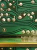
0314221854a.jpg Well I'm running into major problems and I think I bit off way more than I can chew doing this.

I have three bags of parts like I told you before once marked 700 marked 600 one is marked 400. I'm on my last two parts in the 700 bag can't find them for the life of me I can't find where they go I've spent the last hour with a flashlight looking at everything inside this amp and the schematic online can't find it.

There's got to be a better way to do this than the way I'm basically just pulling parts of out of a bag scanning the entire board looking for them. Noticed attached images can't find them after an hour of searching I give up.
 
Last edited:
Well i have decided to push on and keep going with the install. Dont know how to fix a lifted tracer, but that is for sure the problem, will have someone fix it for me. Im finding the method of doing this very very hard, i 3 bags of parts and i have 2 parts left from the first bag and cant find a 22uf 16v for the life of me i have searched the whole board. It may take me weeks to complete this.

:no: Always fix whatever is broken before continuing. The more parts you replace will make 10x harder to fix it later.
Lifted trace are not that hard to fix, post some pictures and we can point you in the right direction. There are many ways to fix it, check this thread.
How to fix this lifted pad? | Audiokarma Home Audio Stereo Discussion Forums
 
Okay sorry I'm just a bit frustrated I'll post a picture of it you can take a look at it I'm 99.8% sure it's a lifted Trace.
 
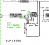
The KS1845 is most probably replacement for the 2SC1685 in the power supply area. I would recommend not to change it and keep it as a spare since the original one is working.

upload_2022-3-14_19-13-45.png
 
Last edited:
How Many CAPACITORS Does The Unit Have ?
$ 60.00 kit - sounds to me - ( IMO ) - possibly 25 capacitors ?

A Partial Set Replacement Is Fine with concentration and focus on ALL the Power Supply and ALL Larger Capacitance Values.

Large Capacitor physical placement and secure - may want a Try @ a small amount of Clear Epoxy or larger dab / @ Automotive RTV , Automotive Gasket Sealant, Liquid Nails Sealant ( (Clear) , Multipurpose Window Caulk.
 
Last edited:
The reason for not having caps or other parts for the tuner section is once you replace caps and or other parts, it can throw the tuner out of alignment.
It may be a bit out of alignment after all these years, but it could wind up being far worse if you go mucking about in the tuner section. As a general rule I don't touch anything in the tuner section of a receiver unless something has failed.
With stand alone tuners I usually will only refresh the power supply only.
I did make a slight asjustment with one tuner I have that has an auto lock circuit. But but before finding out exactly what slug to tune, touched nothing else. Without alignment equipment and experiance in alignment, I just don't mass with tuners.

There are no electrolytic caps that mess with tuner alignment. Stereo multiplex adjustment, maybe, but not the front end.
 
Don't worry. Take a break and come back at it later. Do you have a multimeter? Measure if there is continuity between these two points. If there is continuity then you are good.

upload_2022-3-14_19-25-24.png

To fix the lifted pad, you could make an eyelet with a discarded capacitor lead, scrape off the insulator of the PCB until the copper is exposed and solder the eyelet to the PCB like this.
upload_2022-3-14_19-30-16.png

Or you can solder a jump wire between these to points.
upload_2022-3-14_19-30-1.png
 
ok

Here you go, and thanks a million to everybody for helping me.

100 uf 25v.........3.3 uf 50-....0,47 100- ......those are wima caps.......A992......c1845......1uk63......33uf 50v.......100uf 50v.....47uf 50v......470uf....63v
 
Last edited:
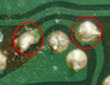
A couple of things to check, be sure cap was installed with negative to where negative was, seems simple enough but I admit to have done this when rushing through. 2cd, reflow those blobs of solder, its should look smooth and shaped like a volcano like the other solder joints from the factory. Put your tip on existing solder and make contact with both the pad and lead then pull tip straight off the joint. I used to end up with blobs like that until I stared using thinner gauge solder. Takes 1 second to reflow so worth a shot.

Be sure to check the continuity on other side of capacitor also as that solder joint looks worse.
 
What soldering iron are you using, too hot and you burn up traces but too cold leaves blobs and can burn traces also because you end up having to leave on pads longer. .

What gauge solder are you using?
 
Back
Top Bottom