• The move to the new server is done. There are some software and database maintenance updates in process. This has us passing the hat around to help out. We appreciate any donations. Seriously, even a dollar helps. The payment page may be found here - https://www.audiokarma.org/support.html

Heathkit W6 testing and issues

nerdorama

AK member
Subscriber
A friend asked me to look at his W6 amps as they don't seem to sound good and lesser amps will outplay them both in quality and the ability to drive speakers.

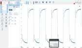
I found the 12AX7 and 12BH7 to be not very well balanced side to side and a bit weak. Found some stronger and better balanced tubes in my stash. Reset bias and they are making pretty close to the rated power of 70W on a sine wave. The 10kHz square waves are quite raggedy on the leading edge. These amps have been very well restored with good quality components and good workmanship.

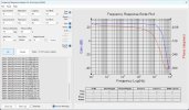
It seems like they may need to have the feedback and response tuning adjusted for a cleaner 10k square. This can cause a somewhat harsh character to the treble when like this. Has anyone in AK land ever dug into one of these and measured this behavior and managed to clean it up? FR is pretty clean and extended.
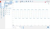
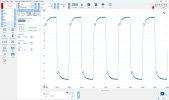
1kHz square 1W voltage level.jpg10kHz square 1W voltage level.jpgW6 FR 8ohm 1W stronger tubes.jpg
 
Register to hide this ad
I'd doubt you could really discern a treble issue, based on the 10kHz squarewave response.

Were you able to get close idle anode current levels in the 6550's? Did that condition also align with minimum output signal harmonic levels, or did that require some offset of bias a bit ?

Component tolerances may not be a concern if new parts have been retrofitted, although that does assume value matching was also done for certain caps and resistances, and valves.

I guess you could play with the value of the nominal 47pF feedback to see its influence on the squarewave leading edge response, as well as the current feedback pot setting. The operating manual 10kHz squarewave response doesn't show what you are reporting.
 
Last edited:
I set the bias current by disconnecting the meter, which is not accurate and clipping the meter leads into my Fluke meter. Not sure how THD stacks up. Guess I should check that. The Picoscope will do a THD in the spectrum mode.

I thought I might disconnect the shelf network and possibly the 47p and see how the FR stacks up with just the feedback resistor and then do some tuning sort of from scratch. The 10k square doesn't resemble that shown in the original manual so it makes me wonder what is happening in this amp. Probably should double check all of the component values since it was completely rebuilt.

Thanks for your comments. Looking for any insight I can get.
 
I haven't used my picoscope for harmonic level assessments - it was too clunky compared to a soundcard and spectrum analyser software.

Sounds like you'll be expending some effort. As such, may be worthwhile doing a benchmark FR with feedback disconnected, and with default feedback and no load (as per the manual).
 
I can do those tests. I thought about starting with no feedback so I could see how much the factory circuit is applying.
 
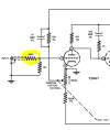
Looks a fair bit of roll-off, its showing up in the sine response past 10khz too. Before you get too deep, make sure that 390K at the input isn't just way out to lunch. Its an awful big resistor to begin with, if its gone high in value it will add HF roll-off. May be able to fix this with a small value cap bridged across it to flatten out the response. Just have to be careful to not go too big and boost the highs, or find out why they used such a big resistor in the first place.

1773632033020.png
 
All of the components are very new. I measured that 390k and it is very close. I also tried jumpering it out just to see what would happen. The 10k square wave got worse and more ragged.
 
hm, interesting. The resistor works with the Miller in the tube to create a low pass, so some extra ringing wouldn't surprise me but I'd expect the leading edge to not be as rolled off.

and I think I misread that response plot, its close to flat out to 100khz, then rolls off right? One of these days I'll learn how to count zeros.

anyway if thats fairly flat out to 100khz, that square looks worse than I'd expect for that response. I have things that roll off well before that and it doesn't have that weird of a rising edge.
 
I’m gonna back it up today. Remove all the compensations and the feedback and start from scratch and see what I can learn. It surprises me that this conforms with the schematic, but not the performance results shown in the old manual.
 
I only have one in my hands right now. I can only assume at this point, but they were restored identically.
 
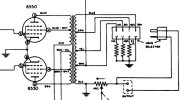
I wonder whether this issue is due in part to the "damping factor control" system? Gotta say, I'm not a fan of the resistance this adds in series with the load. Also wonder whether the secondary transformations are accurate without those resistors at the impedance selector plug and common. I think you'll need to find someone with specific W6 experience to track this down (that excludes me).

Screenshot 2026-03-16 at 10.21.46 AM.png

Jack
 
That 390k resistor in series with the input has me wondering, especially since it is upstream of the 1M grid reference so it makes a voltage divider at the input rather than just a grid resistor to work against the Miller capacitance. I'm wondering about changing the order of the connection for one thing to try. The other version of the W6 has a pot at the input without a separate Miller grid resistor.

Jack,
That damping control does affect the overall feedback level as evidenced by the changing of the peak voltage as I turn the control. My measurements were all with the control at max damping so seems like it should have minimal effect. I've thought about bypassing it. When I was looking at a 1k sine at just over 30W I twisted the control and as I got further away from max the wave shape distorted so I left it at max.

Back on it today. I'll post any interesting or baffling results.
Thanks
 
yeah that should bypass the current feedback part of the equation if the pot is set to whatever direction has the wiper grounded, but the resistance between ground and the load is always there.

current feedback was a thing for a while, then faded away for reasons. Probably measures worse but I have no idea what it sounds like. There were debates on matching the amp's output impedance to the speaker for max power delivery vs max voltage delivery or whatever. Speaker impedance curves being what they are though, thats kind of an impossible thing to really do.

easy enough to wire around though, speaker common straight to ground, positive to whatever impedance tap, then the rest of it doesn't matter and can be abandoned in-place. May want to confirm the output impednace makes sense though, looks like on the 4 ohm side its the 10 ohm pot in parallel with an 11 ohm resistor, so an extra 5.5 ohms resistance in series with the speaker load. Can't quite make out the other resistors but you get the idea.
 
I only have one in my hands right now. I can only assume at this point, but they were restored identically.

I ask because I wonder if there's been some degradation in the output transformer. Either that or the feedback system is messed up, as Jack suggests. Have you checked the Peerless's primaries? You might want to get your hands on the other amp before you drive yourself nuts trying to diagnose this one.
 
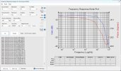
A few more trials. Haven't gotten a result I like but I sure can change the behavior. Can't try it without the compensation components and only the feedback resistor. Oscillates wildly. Even with the phase advance cap added it still oscillates. Have to have some sort of shelf network connected for stability. In just about every case I've tried including the schematic values there is a turnover point around 10k or 15kHz where the level shelves down slowly until some higher freq where it rolls off. This was a trial with a smaller phase advance cap and a 100k resistor in parallel with the 390k at the input. That shelf step of a few dB seems to always be there. Don't have an explanation in my mind yet.
FR 22p fdbk cap reg shelf 100k input.jpg
 
One modification I did was to change the order of the input series and parallel resistors so the 390k is directly to the grid and the 1M is across the input jack side which more closely matches the version of this amp which has an input volume control. This sidesteps the voltage divider caused then they are connected the other way around. Don't know if this a bad move or not.
 
Anyone have a notion about how to interpret a square wave with an initial sharp peak and then a slow rollup after the trailing edge of the peak? This is an extreme example but I can't seem to get the peak and end of the wave to blend smoothly through the trough between them. I can understand that the peak indicates some HF response that lets the leading edge rise quickly but then it seems like a hole in the FR that causes the dip before the trailing part comes up to approx level. I'd like to develop some intuitive understanding of what might cause this and how to implement the fix. If it was stable without the shelf network that I would have a better chance of getting the phase advance cap dialed in better.

W6 10k square 100k input 22p fdbk reg shelf.jpg
 
I think the next step would be to test the small signal frequency response after disconnecting all feedback and compensation. IOW, you would disconnect the wiper of the Damping Factor Control, disconnect the RC compensation at the anode of the first stage, and jumper together all three terminals of the 10Ω pot located at the output transformer common, which is ground. These changes should not create any instability as long as all the bypassing and decoupling components are in good condition.

Jack
 
I disconnected the shelf network and the feedback but the amp oscillated so badly I had to reinstall them to quell it. I did not bypass or disconnect the damping control. It didn't occur to me that jumpering all three connections on the current feedback pot would bypass it completely. Thanks for that. I'll try it. If these pots are wirewound could the inductance in the cathode of the first stage cause an oscillation?
 
Back
Top Bottom