• The move to the new server is done. There are some software and database maintenance updates in process. This has us passing the hat around to help out. We appreciate any donations. Seriously, even a dollar helps. The payment page may be found here - https://www.audiokarma.org/support.html

Heathkit W6 testing and issues

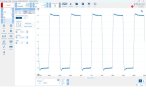
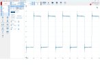
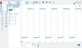
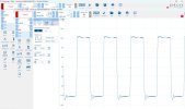
In my opinion, the 10kHz square wave appears over-damped. I prefer to see a slight amount of ringing, which usually indicates the maximum bandwidth possible is being extracted from the transformers. Your response plot does indicate very flat performance to beyond 20kHz, but I think it's falling early. Resonance appears to be way out at 600kHz or so. It might seem that this performance is fine, but in my experience push-pull amplifiers sound better when they haven't been tuned in an effort to make the square wave perfect.

Jack
 
The first-stage shelf starts to influence forward path phase shift from about 4kHz - which appears to be the dominant roll-off, as intended for that technique, as the end frequency is likely prior to hf resonances and any influence on stability margins. Perhaps don't be too quick to change that shelf network, given the effort Heathkit went to, unless you can adequately measure and appreciate all its influences on the performance aspects that Heathkit were looking at and had reported on.

It's good you measured base feedback at circa 21dB, as that indicates they still used the same nominal level out to W-6 and the late 1950's.

Resistor load types have caught a few out over the years, especially if just relying on the sales pitch of 'non-inductive', and coming in a large single case format. You've certainly highlighted one method to test for significant inductance! Another method can use the Picoscope to measure the frequency response of a resistor divider comprising the big resistor in series with a small (say 1W) fixed resistor of the same ohms as the large 'non-inductive' power resistor - the FR should show up a change from 'straight line' gain and phase attenuation heading out to 1MHz. I've used that method to test for non-ideal inductance characteristics of small ferrite inductors out beyond a few 100kHz.

The Heathkit manual indicates stable response for no load, and capacitor-only loading. A Picoscope FR of those load types may indicate how exceptional the stability margin is, and where stability margin may be getting low for particular resonances.

 
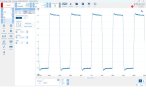
Well, the amps are exactly as the original schematic show them. I can change the tuning for a little bit more overshoot and some of my trials showed that behavior. Mainly changing the phase advance cap to a smaller value does this and extends the FR. Here are some 10k squares with different phase advance cap values. The factory value is 47p.

22p
W6 #1 10kHz sq 10k 22p fdbk and 390k input 1k 910p shelf.jpg
24p

W6 #1 10kHz sq 10k 24p fdbk and 390k input 1k 910p shelf.jpg
30p

W6 #1 10kHz sq 10k 30p fdbk and 390k input 1k 910p shelf.jpg
 
Post #42 comment on first stage shelf was related to post #41 comment about response falling early.

Tuning the feedback comp cap is related to the stability margin out past 200-300kHz (as it has a 340kHz corner frequency when using 47pF), and doesn't impose a falling response out to 100kHz.
 
I measured response changes sub 100k by changing that cap while the shelf network was disabled. I suppose I should try some experiments with the shelf components too.
 
Well, the amps are exactly as the original schematic show them.
Does that include the original damping control circuitry and pots? I'm surprised none of the values you've tried for advance cap produced ringing on the square wave. That may be due to the influence of the shelf network, but perhaps more the result of these transformers exhibiting resonance at such a high frequency.
Perhaps don't be too quick to change that shelf network, given the effort Heathkit went to, unless you can adequately measure and appreciate all its influences on the performance aspects that Heathkit were looking at and had reported on.
I have to agree with this, unless there's concrete evidence that the original values create a problem.

All things considered, it seems you're probably at the end of the road for optimizing these amplifiers. :)

Jack
 
Just for the sake of info sharing here are a couple of experiments along this way. I feel like I'm at a good point to stop and listen to them. If they don't have the sparkle or liveliness then maybe Jack's comment above about tuning for a little less perfect 10k square wave will be an interesting experiment. For now I think trying them with Heathkit's original circuit is a good start.

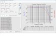
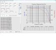
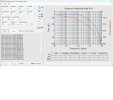
This is no shelf but the 390k input grid resistor and a 22p instead of 47p phase advance. Pretty much a flat trace to 200kHz.
W6 #1 FR 10k 22p fdbk 390k input.jpg
This is completely open loop.
W6 #1 FR all fdbk and comps disconnected.jpg
A 10k feedback resistor and the 390k input resistor. No shelf or phase advance.
W6 #1 FR 10k fdbk and 390k input.jpg
This is 10kHz with no phase adv cap and no shelf.
W6 #1 10kHz sq 10k fdbk and 390k input.jpg
 

Attachments

  • W6 #1 FR only 390k input.jpg
    W6 #1 FR only 390k input.jpg
    101.7 KB · Views: 22
Very cool.
I’ve had my W5’s since the early 90’s and have never stumbled upon these W6. Or W7.

I think it would be fascinating to try these triode connected with no global feedback.
The cathode follower grid drive would handle the grid miller C quite well.

Ron
 
Only problem for me now is I can’t pick them up. I’m under a 5 lb lifting restriction for another eight weeks. I have to have my friend come over and move them for me.
 
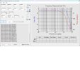
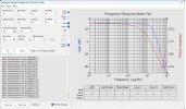
Since I'm stuck at home these days I can't leave well enough alone. I played with some smaller values of the shelf network cap. Factory is 910p. I tried 750, 650 and 390p. They all allowed for a bit more HF extension. If I make this change I'll probably go with the 390p. I checked for stability with a 0.1uF across the 8ohm load resistor and the wave is still well damped and HF extension is more extended. A little ringing on the 10k square.

W6 #1 FR 10k 47p fdbk and 390k input 1k 390p shelf.jpg
1kHz
W6 #1 1kHz 10k 47p fdbk and 390k input 1k 390p shelf.jpg
10kHz
W6 #1 10kHz 10k 47p fdbk and 390k input 1k 390p shelf 8ohm.jpg
10kHa with 0.1uF across 8ohm load
W6 #1 10kHz 10k 47p fdbk and 390k input 1k 390p shelf 8ohm 0.1uF.jpg
 
Last edited:
I have a question about the FR plot I posted just above. I only tried different values of the cap in the shelf network. The FR shows a shallow rolloff before the big fall above 100k. Would adjusting the resistor allow for a more flat response until the big rolloff? I'm still learning this stuff and don't have a good intuitive feel about the behavior of the shelf network.
Thanks
 
In my opinion, the 10kHz square wave appears over-damped.
Hi Jack,
Thanks for your comments and suggestions along the way. At this point would you be inclined to stay with the factory values or try the smaller value shelf network cap and allow some peaking and small resonances?
Thanks
 
Hi Jack,
Thanks for your comments and suggestions along the way. At this point would you be inclined to stay with the factory values or try the smaller value shelf network cap and allow some peaking and small resonances?
Thanks
Based on all your test results, I don't see a compelling reason to make changes. Has DG worked with this amp on the bench? Either Dave or someone with his level of experience could be helpful at this point.

Jack
 
Post #52 plot shows a smooth phase change out to about 180kHz. The squarewave response with 8//0.1uF indicates a dominant ring out at circa 180kHz. To me, the resonance of around 180kHz is what you are 'playing' with when adjusting the comp cap as that cap is shifting the phase a bit out at and past 180kHz, where the stability margin is being changed in a minor way. Adjusting the comp cap is not about altering the roll-off response prior to the resonance, and imho that shouldn't be seen as a target of any comp cap adjustment.

You may get a better insight into the stability margin characteristic (other than the squarewave ringing) if you plot the no load, and the cap-only load responses, as they will likely show peaking in the frequency response out around 180kHz (or lower for cap only loading as the cap load likely lowers the resonance frequency). Obtaining measured responses of that resonance imho provides good evidence of what the OPT is like, and how stable the amp is. It could even allow you to increase the feedback level if you really wanted to go that path.

Below the 180kHz resonance, the frequency and phase response is mainly influenced by the step filter - which is then an interplay on how that filter impacts on the audio band (at the low end) and on the stability margin (at the high end).
 
The owner of the W6's came to reclaim them tonight. We had about 2 hours of listening to them. They are glorious sounding and powerful. The only change I made in the end was removing the damping circuit. Happy ending. Might have to get a pair for myself. Thanks to all for the comments, advice and encouragement.
John
 
Back
Top Bottom