after connecting C301 and measuring dc, the C301 input is 55V instead of 86V? I didn't measure it in the previous test,I think the next step is to put the new cap in place of the old one and clean up the wiring. After that test again and if still OK then install the plug "A" for the amp power and test again. It certainly looks like C301 was the root of your problems.


You are using an out of date browser. It may not display this or other websites correctly.
You should upgrade or use an alternative browser.
You should upgrade or use an alternative browser.
Kenwood Ka6000
- Thread starter Dart07
- Start date


Is that with the DBT? Wattage Size of bulb? (just looked back and it looks like you use 70 watts) Do you have a 100 watter?after connecting C301 and measuring dc, the C301 input is 55V instead of 86V? I didn't measure it in the previous test,
Is plug "A" out or in?
Check the secondary AC voltage Red to Red out of the transformer. Looking for 65 VAC.
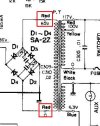
red to red is 47VAC, I am looking for a 100W bulbIs that with the DBT? Wattage Size of bulb? (just looked back and it looks like you use 70 watts) Do you have a 100 watter?
Is plug "A" out or in?
Check the secondary AC voltage Red to Red out of the transformer. Looking for 65 VAC.
View attachment 3503822
red to red is 47VAC,
Are you testing with the DBT?
Is plug "A" in or out?
plug is out, i connected bulb 150W and stil is 65V on c301 , red to red 56VAC, maybe without bulb will be 65VAC ?? and there is no 8V on blue wire for lightsAre you testing with the DBT?
Is plug "A" in or out?
Last edited:
The lamps are AC voltage form the blue wire. Measured from blue to chassis looking for 6.3 VAC.plug is out, i connected bulb 150W and stil is 65V on c301 , red to red 56VAC, maybe without bulb will be 65VAC ?? and there is no 8V on blue wire for lights

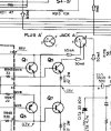
that's right, it's 6.3VAC and 81V on C301 without plug A, measurement error... I checked the small transistors from the overheated channel and one pair is damaged Q1, Q3 , the other is ok. are there any TO66 substitutes? 2SA566, 2 SD680The lamps are AC voltage form the blue wire. Measured from blue to chassis looking for 6.3 VAC.
View attachment 3503859
Pictures of the Q1 & Q3 area so I can see what you are working with.that's right, it's 6.3VAC and 81V on C301 without plug A, measurement error... I checked the small transistors from the overheated channel and one pair is damaged Q1, Q3 , the other is ok. are there any TO66 substitutes? 2SA566, 2 SD680

I checked the control transistors because after a while of testing without a bulb, smoke came out of that area..., proper photo, sorryPictures of the Q1 & Q3 area so I can see what you are working with.
Attachments

Last edited:
Looks like you have room for the TO-220. I figured you would. I would suggest that you should probably replace all four.I checked the control transistors because after a while of testing without a bulb, smoke came out of that area..., proper photo, sorry
by the way two 2sc898 in this channel were damaged... will 2n3442g be ok? because 2sc1116a are hard to get... their parameters are similar to 2sc898, what do you think ?that's right, it's 6.3VAC and 81V on C301 without plug A, measurement error... I checked the small transistors from the overheated channel and one pair is damaged Q1, Q3 , the other is ok. are there any TO66 substitutes? 2SA566, 2 SD680
I read this thread and hence my doubts... https://audiokarma.org/forums/index.php?threads/help-2sc898-substitute.113227/
possibly MJE21194G ?
2N3442G Datasheet and Replacement
Type Designator: 2N3442GMaterial of Transistor: Si
Polarity: NPN
Maximum Collector Power Dissipation (Pc): 117 W
Maximum Collector-Base Voltage |Vcb|: 160 V
Maximum Collector-Emitter Voltage |Vce|: 140 V
Maximum Emitter-Base Voltage |Veb|: 7 V
Maximum Collector Current |Ic max|: 10 A
Max. Operating Junction Temperature (Tj): 200 °C
Transition Frequency (ft): 80 MHz
Forward Current Transfer Ratio (hFE), MIN: 20
Noise Figure, dB: -
Package: TO204
Last edited:
mcdoug3721
Super Member
Not many options these days on TO-3 replacements. Most are 4 Mhz. MJ21194G would work. MJ15015G is 6Mhz and looks sufficient if the low frequency is a concern. The originals are 7.5Mhz.

Hi, most of the datasheet says that MJ15015 is 0.8Mhz and not 6Mhz and I don't know which one to buy... there is still 2sc2607 ??Not many options these days on TO-3 replacements. Most are 4 Mhz. MJ21194G would work. MJ15015G is 6Mhz and looks sufficient if the low frequency is a concern. The originals are 7.5Mhz.
Last edited:
My guess is that you are looking at the combo datasheet. And I think the fT min value of .8 is most likely for the 2N3055, or a mistake.Hi, most of the datasheet says that MJ15015 is 0.8Mhz and not 6Mhz and I don't know which one to buy...

Here is the datasheet for just the 2N3055, fT of 2.5 min

So I can see where it can be confusing.
The MJ15015's are not in stock at the big two. 2N3055's are in stock.
My gut says that the KA6000 is not a "high"speed" design and the 2N3055's would be just fine.
Or you could just go with MJ21194 and call it a day. fT is 4MHz. They cost a couple bucks more.
I'm looking for another equivalent... in the end I will probably buy 21194 anyway...My guess is that you are looking at the combo datasheet. And I think the fT min value of .8 is most likely for the 2N3055, or a mistake.
View attachment 3508306
Here is the datasheet for just the 2N3055, fT of 2.5 min
View attachment 3508307
So I can see where it can be confusing.
The MJ15015's are not in stock at the big two. 2N3055's are in stock.
My gut says that the KA6000 is not a "high"speed" design and the 2N3055's would be just fine.
Or you could just go with MJ21194 and call it a day. fT is 4MHz. They cost a couple bucks more.
BDY56 ?? (Pc): 115 W, |Vcb|: 150 V, |Vce|: 120 V, |Veb|: 7V, |Ic max|: 15 A, (Tj): 200 °C, (ft): 10 MHz, (hFE), MIN: 20
Last edited:
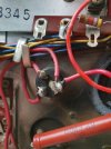
I wonder about one more thing... why are these two pins plug A connected... in other pictures they are separate... and in this case the current goes directly to the transistors...?? maybe that's why this channel overheated so much??
I'll separate these two pins...
I'll separate these two pins...
Attachments

Semanon
Super Member
Electrically, Plug A simply shorts all those wires together, and the current goes directly to the transistors (and other places). Separating them would not make any difference.

The prevailing sentiment here amongst experienced techs and restorers is to fix the immediate problem before making other changes. While it’s tempting to fiddle around ‘while it’s open’ and waiting for parts, by making other changes you complicate the situation, sometimes exponentially.
If it was working or close to working before you started repairs, and the red plug shows no sign of being part of the problem, leave it alone. It’s just a shorting plug and jack. Very little can go wrong, most people don’t require it, and the soldering looks original.
Actually that looks like it may be a factory change where they connected 3 and 4 together so the driver circuits have power with the plug in or out.Electrically, Plug A simply shorts all those wires together, and the current goes directly to the transistors (and other places). Separating them would not make any difference.
View attachment 3508954
The prevailing sentiment here amongst experienced techs and restorers is to fix the immediate problem before making other changes. While it’s tempting to fiddle around ‘while it’s open’ and waiting for parts, by making other changes you complicate the situation, sometimes exponentially.
If it was working or close to working before you started repairs, and the red plug shows no sign of being part of the problem, leave it alone. It’s just a shorting plug and jack. Very little can go wrong, most people don’t require it, and the soldering looks original.
It would certainly make it easier to perform the bias adjustments.
The manual calls for you to short 3 & 4 together after you remove the plug, so having them already connected at the jack makes sense.
I agree leave it alone.
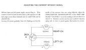
Just curious can you see how your plug "A" is wired.
ok, I'm not touching itActually that looks like it may be a factory change where they connected 3 and 4 together so the driver circuits have power with the plug in or out.
It would certainly make it easier to perform the bias adjustments.
The manual calls for you to short 3 & 4 together after you remove the plug, so having them already connected at the jack makes sense.
I agree leave it alone.
View attachment 3509023
Just curious can you see how your plug "A" is wired.
View attachment 3509021