• The move to the new server is done. There are some software and database maintenance updates in process. This has us passing the hat around to help out. We appreciate any donations. Seriously, even a dollar helps. The payment page may be found here - https://www.audiokarma.org/support.html

Kenwood Ka6000

I'm looking for another equivalent... in the end I will probably buy 21194 anyway...
BDY56 ?? (Pc): 115 W, |Vcb|: 150 V, |Vce|: 120 V, |Veb|: 7V, |Ic max|: 15 A, (Tj): 200 °C, (ft): 10 MHz, (hFE), MIN: 20
BDY56 has less than half of the power (heat) dissipation of the MJ21194. If you are concerned about heat you should be looking at something beefier than BDY56.
 
the amplifier is in the works but now I would like some advice on the tuner from this set... when I turn it on the fuse blows every time... where to start in the power supply section...
probably both devices were connected to one socket and both failed, in ka-6000 the main capacitor and a few other elements were damaged and now I have to find the fault...
 

Attachments

  • 1749715094328369667550699368711.jpg
    1749715094328369667550699368711.jpg
    134.4 KB · Views: 5
  • 17497151382003238144752918032846.jpg
    17497151382003238144752918032846.jpg
    118.1 KB · Views: 5
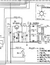
The power supply in the KT-7000 is pretty simple. Any of the components could cause a short causing the fuse to blow. Try to identify which component is the culprit. It could be several if this was a power line surge. Test caps, diodes, the regulator transistor, and the zener. You may need to pull some of the components out of the circuit.
IMG_0752.jpeg

My money is on a shorted cap followed by a bad diode.
 
Last edited:
the amplifier is in the works but now I would like some advice on the tuner from this set... when I turn it on the fuse blows every time... where to start in the power supply section...
probably both devices were connected to one socket and both failed, in ka-6000 the main capacitor and a few other elements were damaged and now I have to find the fault...
hello, I'm back with a report... replaced capacitors, started by a light bulb for about a minute it was ok, then I turned the scale and again emergency mode, i.e. light bulb with full brightness but this time the fuse is intact. What to check now, can the movement of the scale indirectly cause a short circuit?
 

Attachments

  • 17508418004858746000731726349970.jpg
    17508418004858746000731726349970.jpg
    160.6 KB · Views: 10
Last edited:
hello, I'm back with a report... replaced capacitors, started by a light bulb for about a minute it was ok, then I turned the scale and again emergency mode, i.e. light bulb with full brightness but this time the fuse is intact. What to check now, can the movement of the scale indirectly cause a short circuit?
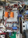
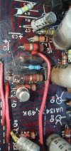
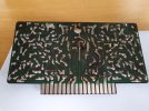
Hello, after removing the amplifier board, there are already significant signs of burn-in and previous repairs. I replaced the burnt-out R945 33R. I'll also replace the ones next to it because they're very hot. What could have caused this?

KT7000 after replacing a few capacitors it already works beautifully.
 

Attachments

  • 20250728_095738.jpg
    20250728_095738.jpg
    104.8 KB · Views: 6
  • 20250728_095726.jpg
    20250728_095726.jpg
    100.7 KB · Views: 6
  • 20250728_095750.jpg
    20250728_095750.jpg
    104.4 KB · Views: 6
Hello, after removing the amplifier board, there are already significant signs of burn-in and previous repairs. I replaced the burnt-out R945 33R. I'll also replace the ones next to it because they're very hot. What could have caused this?

KT7000 after replacing a few capacitors it already works beautifully.
C 923 and 924 in the specification 100uF 50V, in the board there were 47uF 50V and I soldered them in, what about yours, 100 or 47??
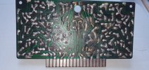
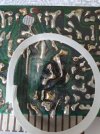
Is this path connected correctly? Please verify. foto 3 .
 

Attachments

  • 17537775248874150074305810841519.jpg
    17537775248874150074305810841519.jpg
    116.8 KB · Views: 2
  • 17537775501471714329775225869246.jpg
    17537775501471714329775225869246.jpg
    152.3 KB · Views: 3
  • 17537776688165500613317769609017.jpg
    17537776688165500613317769609017.jpg
    151 KB · Views: 2
  • 17537793641894066053437068231714.jpg
    17537793641894066053437068231714.jpg
    185.8 KB · Views: 2
movement of the scale
Can you tell me what you mean by 'movement of the scale'? Volume control?

It's been a while, and I'm lost. I thought it the short was solved and the amp was working. Can you summarize how we got here and the work you've done? Listing them in the order you did the work will help.

Which caps did you replace in the tuner? It helps others who experience the same situation.

Specific thoughts:

- Ia that a 1/4 watt resistor? The original was 1/2 watt. May spell trouble.

- R945 seems to be the emitter resistor for the driver transistor Q1. You will need to pull it and test Q1 (and probably Q3, too). The original is a TO-66, so a TO-220 will be a replacement, if needed.

- C921, 922, 923 and 924 have been replaced. If the installed caps don't match the schematic, replace them with correct ones. Mine are the same as the caps listed in the service manual.
1753780239746.png

- Q7 has been probably been replaced. Given the attention to detail from the other repairs, it worth checking if the replacement is a good selection for the job.

- For the PCB trace, check it with a meter for continuity. If it's not good, bedn a cut-off capacitor lead and solder it over the existing trace. Regardless, that solder is worth removing (solder sicy or suction) and reflowing.


After you get all the other things working, you can improve the sonic quality by doing the following. It is usuallr recommended that improvements shuld wait unitl all problems are completeely resolved.
  • Replacing the 2SC458 ttansistors with KSC1815 or KSC1845. The 1815 is lower gain, but the KA-6000 has an odd gain structure and the 1845 can create some minor problems. Experimentation is key with thei amp.
  • Replace all the 1/2 watt carbon comp resistors wiht metal film
  • Recap and use film caps for values under 3uF.

 
Can you tell me what you mean by 'movement of the scale'? Volume control?

It's been a while, and I'm lost. I thought it the short was solved and the amp was working. Can you summarize how we got here and the work you've done? Listing them in the order you did the work will help.

Which caps did you replace in the tuner? It helps others who experience the same situation.

Specific thoughts:

- Ia that a 1/4 watt resistor? The original was 1/2 watt. May spell trouble.

- R945 seems to be the emitter resistor for the driver transistor Q1. You will need to pull it and test Q1 (and probably Q3, too). The original is a TO-66, so a TO-220 will be a replacement, if needed.

- C921, 922, 923 and 924 have been replaced. If the installed caps don't match the schematic, replace them with correct ones. Mine are the same as the caps listed in the service manual.
View attachment 3562702

- Q7 has been probably been replaced. Given the attention to detail from the other repairs, it worth checking if the replacement is a good selection for the job.

- For the PCB trace, check it with a meter for continuity. If it's not good, bedn a cut-off capacitor lead and solder it over the existing trace. Regardless, that solder is worth removing (solder sicy or suction) and reflowing.


After you get all the other things working, you can improve the sonic quality by doing the following. It is usuallr recommended that improvements shuld wait unitl all problems are completeely resolved.
  • Replacing the 2SC458 ttansistors with KSC1815 or KSC1845. The 1815 is lower gain, but the KA-6000 has an odd gain structure and the 1845 can create some minor problems. Experimentation is key with thei amp.
  • Replace all the 1/2 watt carbon comp resistors wiht metal film
  • Recap and use film caps for values under 3uF.
'movement of the scale'?It was about the tuner scale pointer, it has already been repaired.
- R945 is 0,6W
- Q1-Q4 i will changed it to mj15035g , 15033g
"
- C921, 922, 923 and 924 have been replaced. If the installed caps don't match the schematic, replace them with correct ones. Mine are the same as the caps listed in the service manual. My board is 1343, K49, in manual is 1343 K1, 47UF was been "sitting" since new, they don't look like they've been replaced...but I will exchange it for 100uF
I'll replace the capacitor one by one, as you wrote. I don't want to do too much at once so I don't get confused. I want to get it running without any surprises and then renew it.
 

Attachments

  • 17537973360307082759704280066720.jpg
    17537973360307082759704280066720.jpg
    92.5 KB · Views: 5
  • 17537973614688099046565890956078.jpg
    17537973614688099046565890956078.jpg
    123.3 KB · Views: 5
Last edited:
'movement of the scale'?It was about the tuner scale pointer, it has already been repaired.
- R945 is 0,6W
- Q1-Q4 i will changed it to mj15035g , 15033g
"
- C921, 922, 923 and 924 have been replaced. If the installed caps don't match the schematic, replace them with correct ones. Mine are the same as the caps listed in the service manual. My board is 1343, K49, in manual is 1343 K1, 47UF was been "sitting" since new, they don't look like they've been replaced...but I will exchange it for 100uF
I'll replace the capacitor one by one, as you wrote. I don't want to do too much at once so I don't get confused. I want to get it running without any surprises and then renew it.
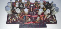
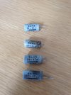
Two 100uF capacitors installed, plus two 2SC281 transistors replaced with KSC1815s. The traces are severely burned and coming off the board. I'm fiddling with and extending them with wire. Now I need to test whether the above mentioned components work... How can I measure this without assembly to eliminate soldering errors? Is there a way? Compare the two channels...
I want to buy a main amp board in better condition if I can find it somewhere... this one doesn't inspire confidence anymore...
 

Attachments

  • 20250731_123712.jpg
    20250731_123712.jpg
    115.9 KB · Views: 5
  • 20250731_123703.jpg
    20250731_123703.jpg
    107.7 KB · Views: 6
I assembled and connected the amplifier, the light went out. I tested the DC voltage at the terminals, and it's high... 8V and not dropping. Please for simpler instructions on setting the bias and DC offset. I have the manual, but it's very complicated... I don't have an oscilloscope and a dummy load as described in the manual... I can build a dummy load but maybe it can be done without it

thanks, i already finded in another thread
R272 left of right on foto ?
C171,271 can 3300 100v capacitors be used instead of 50v?
After a few minutes of operation, the left channel gets very hot, the heatsink is untouchable... For the duration of the repair, I installed 2N3055 transistors. Where can I look for the cause of this heating?
 

Attachments

  • 17545697116847749146550893448009.jpg
    17545697116847749146550893448009.jpg
    105.6 KB · Views: 5
Last edited:
I tested the DC voltage at the terminals, and it's high... 8V and not dropping. Please for simpler instructions on setting the bias and DC offset.
It is a cap coupled amp. You can’t test DC offset like you would with a direct coupled amp. You need a load. Adjustment procedure in the service manual is what I followed. There are some other methods, but you will need to Google to find them.
 
It is a cap coupled amp. You can’t test DC offset like you would with a direct coupled amp. You need a load. Adjustment procedure in the service manual is what I followed. There are some other methods, but you will need to Google to find them.
Thank you, now I'm more interested in why this channel gets so hot?
 
It is no doubt hot because the bias is too high. Don't operate it for long periods running that hot, you will fry something eventually.

Show us with pictures how you set up to measure and adjust bias?

Did you check and adjust if needed the DC center voltage? Note: Not DC offset, as has been said this amp does not have offset adjustments.

There is another way to measure bias if you have easy access to the .47 ohm 2W emitter resistors for the output transistors. I can't tell from the manual but they may be part of the heatsink assembly? Again pictures tell the story
 
It is no doubt hot because the bias is too high. Don't operate it for long periods running that hot, you will fry something eventually.

Show us with pictures how you set up to measure and adjust bias?

Did you check and adjust if needed the DC center voltage? Note: Not DC offset, as has been said this amp does not have offset adjustments.

There is another way to measure bias if you have easy access to the .47 ohm 2W emitter resistors for the output transistors. I can't tell from the manual but they may be part of the heatsink assembly? Again pictures tell the story
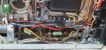
I haven't adjusted anything yet, I checked the DC on the terminals and as you can see it's incorrect... access is good R172 left or right ?
 

Attachments

  • 17546538558552606709242037478884.jpg
    17546538558552606709242037478884.jpg
    101.5 KB · Views: 3
I haven't adjusted anything yet, I checked the DC on the terminals and as you can see it's incorrect... access is good R172 left or right ?
There should be 4 of them. That appears to be one from each channel. Can you see two others from the top side?
 
It is no doubt hot because the bias is too high. Don't operate it for long periods running that hot, you will fry something eventually.

Show us with pictures how you set up to measure and adjust bias?

Did you check and adjust if needed the DC center voltage? Note: Not DC offset, as has been said this amp does not have offset adjustments.

There is another way to measure bias if you have easy access to the .47 ohm 2W emitter resistors for the output transistors. I can't tell from the manual but they may be part of the heatsink assembly? Again pictures tell the story

There should be 4 of them. That appears to be one from each channel. Can you see two others from the top side?
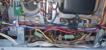
yes, two others is on the right chanell
 

Attachments

  • 17546562187038338950121598794085.jpg
    17546562187038338950121598794085.jpg
    121.5 KB · Views: 2
Go it two different sides, not top and bottom. The left channel has had the resistors replaced and the right looks original.
yes, but I still don't know which one it is, R 172/R272... I think it's the one on the left in the photo, closer to the front..?
 
I know you have a DBT, we will want to use it at first. I think we should start with the left channel. We are looking at Q5 and Q7.

6000bot.jpg

6000q5_q7.jpg
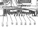
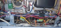
The leftmost resistor is for Q7 and is R172. The right resistor is for Q5 and is R 171.

Lets check the DC balance real quickly to make sure we are in the ballpark. Set your meter for DC volts clip the + lead to the left side of the Q5 resistor.
Be careful not to short that left lead to the terminal strip or the screw head. It looks close to the screw but it could just be the angle.

Clip the minus side of the meter to the chassis. Using the DBT turn the unit on and look for a DC voltage in the neighborhood of 43 volts.

Turn it off and report back. Also a nice closer picture of the bottom of the other channels heatsink please.
 
Back
Top Bottom