• Please note that Audiokarma will be offline briefly for updates early on Monday morning, September 28th.

KLH model six acoustic suspension speakers question

Thank you RTally for your reply.
If I am reading the schematic properly, C and B are the positive with A the common negative. I had printed this previously from the same link which I had compared to the KLH 17 schematic (provided on this forum from a discussion I am not sure of). This is how I knew the component values were the same and the value of the inductor coil on the positive woofer lead.
My KLH 6 crossover has only the 2-terminal positive and negative and not the earlier 3 terminal input.
I did not re-wire the crossover at all. I just checked it to determine if they were good before trying my drivers on them.
I am confused now regarding your instructions regarding reading values at the speaker terminals. I just received 6.8 to 7.0 ohm readings of the existing KLH 17's taken at the positive and negative speaker terminals. I received similar values from a pair of KLH 22A's. and the 6/17's I created.
None connected to an amp. And when connected, they all sound fine. I do not think the capacitors are a problem.
I just read 4.4 ohms on the inductors only. I am referring to this component as that, though I am not certain of what it is. I am going by the .4 MH value of the schematic. I also do not know how to obtain an MH value with a meter.
I also tried non KLH 8 ohm drivers, Woofer 9.8 ohm, tweeter 9.1 ohm, reading 10.1 ohms at the terminals without the inductor and 4.5 ohms with the inductor.
I cannot be certain that I have not mis-wired again, but the results are consistent with the KLH drivers. At the very least, I think I know now that the KLH 17 woofer being different than the KLH 6 woofer is not causing the drop in resistance. Including the inductor as intended or removing it from the circuit is not that difficult to wire, since the circuit itself is so simple. And both the tweeter and the woofer worked wired both ways.
Can an inductor fail like a capacitor, as I believe they both serve a similar function as a filter or choke?
I am obviously not an electrician, just someone with very little knowledge (I know a little knowledge can be dangerous, in this hobby that means expensive) but with a desire to understand and make things work without causing any damage to these valuable KLH components.
Your insights and help are very much appreciated!
 
Thank you RTally for your reply.
If I am reading the schematic properly, C and B are the positive with A the common negative. I had printed this previously from the same link which I had compared to the KLH 17 schematic (provided on this forum from a discussion I am not sure of). This is how I knew the component values were the same and the value of the inductor coil on the positive woofer lead.
My KLH 6 crossover has only the 2-terminal positive and negative and not the earlier 3 terminal input.

It sounds like you have a later version Model Six, probably 1975 or 76. See https://audiokarma.org/forums/index.php?threads/klh-model-six-rule.193462/
My two pair of Model 6 are earlier models (1963 & 1967).

I did not re-wire the crossover at all. I just checked it to determine if they were good before trying my drivers on them.
I am confused now regarding your instructions regarding reading values at the speaker terminals. I just received 6.8 to 7.0 ohm readings of the existing KLH 17's taken at the positive and negative speaker terminals. I received similar values from a pair of KLH 22A's. and the 6/17's I created.
None connected to an amp. And when connected, they all sound fine. I do not think the capacitors are a problem.

With vintage KLH speakers, the capacitors are always a problem, except for very early ones with oil caps.

:needpics:
A picture of the crossover would really help. When we get to see what you are seeing, we can provide much better advice.

I just read 4.4 ohms on the inductors only. I am referring to this component as that, though I am not certain of what it is. I am going by the .4 MH value of the schematic. I also do not know how to obtain an MH value with a meter.
I also tried non KLH 8 ohm drivers, Woofer 9.8 ohm, tweeter 9.1 ohm, reading 10.1 ohms at the terminals without the inductor and 4.5 ohms with the inductor.

It sounds like the inductor may be wired in parallel with the woofer. If the inductor is wired in series as shown in the schematic, the resistance values are added together to get the total resistance.

I cannot be certain that I have not mis-wired again, but the results are consistent with the KLH drivers. At the very least, I think I know now that the KLH 17 woofer being different than the KLH 6 woofer is not causing the drop in resistance. Including the inductor as intended or removing it from the circuit is not that difficult to wire, since the circuit itself is so simple. And both the tweeter and the woofer worked wired both ways.

From your description, my guess is that they are not wired as per the schematic.

Can an inductor fail like a capacitor, as I believe they both serve a similar function as a filter or choke?

Nope. Inductors rarely fail. If they do fail, they will be burnt or show melted parts. They also fail, generally, as an open circuit. Sometimes they may fail with adjacent windings shorted together, which reduces dc resistance and inductance. Capacitors generally fail by having a much increased equivalent series resistance (ESR), which muffles the sound, and/or by a change in capacitance value, which moves the crossover frequency up or down. Sometimes, the caps fail catastrophically, such as by blowing apart. The caps with black bodies and red ends are notorious for failing, sometimes catastrophically.

I am obviously not an electrician, just someone with very little knowledge (I know a little knowledge can be dangerous, in this hobby that means expensive) but with a desire to understand and make things work without causing any damage to these valuable KLH components.
Your insights and help are very much appreciated!

Now is a great time to learn.

Print out the schematic. With only two speaker terminals, the points B and C in the schematic are joined together. Starting with one wire attached to the woofer, trace that wire to see where it goes. Trace the wire on the schematic and see if that wire goes where the schematic says. Do that for every wire. You will learn a lot doing this.

Another way of checking the actual circuit is to draw it out. Start with one wire on the woofer and see where it goes and what it is connected to. Draw it on paper. Pick another wire, trace it, and draw it. I much prefer this method. You can learn a lot by putting your hands and the wire and drawing out what each end is connected to. It does not have to be pretty. My first sketch is always a mess. After I trace every wire, I redraw it to look more like a traditional schematic.
 

Attachments

  • image.gif
    image.gif
    41.6 KB · Views: 15
KLH could have labeled the connections a little more clearly. It would be easy for a user to think the "C" terminal meant "common". Of course, if you have the instructions, fine, but they aren't always there.

Doug

I'd say the jumper wire between B and C is missing.
 
Well, that was easy! You are SO right! Time to learn! 1st lesson; I really did not read the schematic properly and did wire the inductor incorrectly.
The red and black leads out of the inductor threw me off. I was going to snap a picture as you requested but immediately saw my error and corrected it. I did not have the inductor in-line with the positive. But after correction I am not sure how I had it.
I am sorry I provided no photos, but this thread was not worthless to me. You really did solve the problem. The values at the terminals are now correct with the inductor connected. All of my components are functioning correctly. Now I just have to find the KLH 6 woofers and hopefully the tweeters as well.
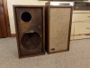
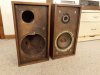
But here are a couple of photos of what started all this.
The cabinets on the left are, of course the real 6's. The ones on the right are my attempts to create a 6 with the KLH 17 components I had from an earlier attempt at cabinet building that did not work out so well. Those were another story but they were larger at 1.2 ft3 than the 17 at .96 ft3. So I tried again but at the actual size of a 6 at 1.46 ft3. These were more successful but if you want them to look like Walnut, USE walnut and NOT Maple (i had left over from another project). I am not a carpenter, I have some skills, but I can tell you that building speaker cabinets that look GOOD is NOT easy!
There is a reason why nobody builds speakers this way anymore! Except for ones at obscene prices. And why there is a community out here that relishes these beauties from the past.
Thanks for all your help!
 

Attachments

  • KLH 6.jpg
    KLH 6.jpg
    103 KB · Views: 26
  • KLH6a.jpg
    KLH6a.jpg
    97.4 KB · Views: 26
I did find and order 2 Model 6 woofers on ebuy and am awaiting delivery. Wow, were they ever expensive! (Relative to the prices I see some of you had purchased a COMPLETE pair of 6's). And the ship costs alone were almost as much as the item itself! I know, I agreed to pay the price, but there does not seem to exist anyplace else to shop for these old parts. A captive market indeed!
I am now preparing an order for the caps from PE also. Which raises several other questions. They appear to have only an 8.2uf cap and not an 8.0uf cap. Will that make a difference? I saw on another thread that a higher cap value could be bad. Also, is the model 6 HF crossover a 1st order? I found a calculator that indicates that an 8uf cap in a 1st order would cross at around 2500 hz. Would the other two 2uf caps in the circuit combine to lower the crossover to (1660 hz) closer to the Model 6 crossover point stated at 1500 hz? Would a 10uf cap (plus 2uf and 2uf = 1420hz) be better to bring the combined value closer to the 1500hz crossover?
Am I thinking too much with too little knowledge becoming dangerous AND expensive?
Really, I do realize that these marvelous speakers were engineered to perfection and WILL leave very well enough alone. I am just needing your expertise to edify my curiosity. I hope I am not taking too much of your valuable time, but this venue is the only place to find the answers!
 
I am now preparing an order for the caps from PE also. Which raises several other questions. They appear to have only an 8.2uf cap and not an 8.0uf cap. Will that make a difference? I saw on another thread that a higher cap value could be bad.

The additional 0.2 uF is 2.5% off from what is installed. That is well within the tolerance of the original caps, which were likely 10% tolerance. The slightly higher capacitance value serves to lower the crossover frequency a slight amount. Such a small change will not be audible.
Alternatively, you could wire two 4 uF caps in parallel to hit the spec'd 8 uF exactly.

Also, is the model 6 HF crossover a 1st order? I found a calculator that indicates that an 8uf cap in a 1st order would cross at around 2500 hz. Would the other two 2uf caps in the circuit combine to lower the crossover to (1660 hz) closer to the Model 6 crossover point stated at 1500 hz? Would a 10uf cap (plus 2uf and 2uf = 1420hz) be better to bring the combined value closer to the 1500hz crossover?

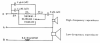
The HF crossover is a first order high pass filter with switchable attenuation (7.5 ohm resistor) and two contour networks (the two 2 uF & 3 ohm resistors). See schematic in post #20. The contour networks slightly change the frequency response of the tweeter. The decrease position adds a complex contour or shaping network that attenuates the lower frequencies and boosts the attenuated upper frequencies for the tweeter. The increase position removes some attenuation (7.5 ohm resistor) and adds a complex contour or shaping network that boosts the upper frequencies for the tweeter. The normal position removes some attenuation (7.5 ohm resistor) and adds a different complex contour or shaping network that boosts the upper frequencies for the tweeter. Choose a switch position that you find pleasing.

Check out this link to learn more about crossovers.

Am I thinking too much with too little knowledge becoming dangerous AND expensive?
Good questions. You learn by asking. :banana:
 

Attachments

  • KLH Model 6 crossover.png
    KLH Model 6 crossover.png
    178.4 KB · Views: 11
I did find and order 2 Model 6 woofers on ebuy and am awaiting delivery. Wow, were they ever expensive! (Relative to the prices I see some of you had purchased a COMPLETE pair of 6's). And the ship costs alone were almost as much as the item itself! I know, I agreed to pay the price, but there does not seem to exist anyplace else to shop for these old parts. A captive market indeed!
I am now preparing an order for the caps from PE also. Which raises several other questions. They appear to have only an 8.2uf cap and not an 8.0uf cap. Will that make a difference? I saw on another thread that a higher cap value could be bad. Also, is the model 6 HF crossover a 1st order? I found a calculator that indicates that an 8uf cap in a 1st order would cross at around 2500 hz. Would the other two 2uf caps in the circuit combine to lower the crossover to (1660 hz) closer to the Model 6 crossover point stated at 1500 hz? Would a 10uf cap (plus 2uf and 2uf = 1420hz) be better to bring the combined value closer to the 1500hz crossover?
Am I thinking too much with too little knowledge becoming dangerous AND expensive?
Really, I do realize that these marvelous speakers were engineered to perfection and WILL leave very well enough alone. I am just needing your expertise to edify my curiosity. I hope I am not taking too much of your valuable time, but this venue is the only place to find the answers!
@RTally is right re: the 8 uF cap. If you want to get as close as possible to 8, then using two 4 uF caps in parallel is the way to go. This is what I did with my early KLH 6. Yes my wiring and tape look ugly, but there is no getting back into these once all the crossover went back into the abyss! So everything needed to be bulletproof.
 

Attachments

  • E21D5C85-AB8E-430F-B0D3-052F50792314.jpeg
    E21D5C85-AB8E-430F-B0D3-052F50792314.jpeg
    102.7 KB · Views: 20
Good stuff! This is great! I think I will stay with the 8.2 uf cap available to keep it simple for me, seeing as how the .2 would not really make a difference. But now I have questions regarding impedance.
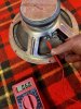
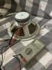
I received my 2 woofers, which look very similar in size and construction. They do appear to be of differing vintage. I do know they are from a Model 6, but the impedance is different on them. One reads 7.8 ohms, the other reads 6.0 ohms. Is something wrong with the lower reading one? Will the differences in impedance alter the sound or render damage to my receiver? I purchased these 2 because they were the only 2 available that looked the same (there was another one, but the front; surround, cone and cap were all grey/charcoal/black? What's up with that!). These woofers do not seem to come up that frequently, at least not in the time I have been searching. Another one was just listed, but that one reads 4.5 ohms. Was there a 4 ohm model 6 available?
KLH 6 woofer d.jpg

KLH 6 woofer n.jpg
I have installed the woofers in the (real) 6 cabinets with the 6 crossovers and the donor model 17 tweeters (which read 7.2 ohms) and they sound fine, although the surrounds need to be doped. But the Vintage AR kit is not available at this time. Does anyone have any experience with the Lexel alternate suggestion? Alternative surround dope ... Lexel - KLH - The Classic Speaker Pages Discussion Forums
Regarding the tweeters, I have read that the Model 6 and 17 used the same tweeters and that the model 20 tweeter was the same as well, but every listing I have seen for those are reading 4 ohms. Will the model 20 tweeter work? I am still searching for correct tweeters to complete the pair of 6's and return the tweeters to the pair of 17's.
 
Don't use the alternative Lexel stuff. They guy did not do any testing to verify that he did not ruin his speakers. Use the real deal. vintage-ar takes off the late winter months. He should be back sometime in March. If you are in a hurry, contact RoyC here. I've bought my surround dope from him directly.

I would not worry too much about the dc resistance difference, particularly if the two speakers sound the same. I only use dc resistance measurements to ensure that there is not an open circuit. As for your measurements, 6 ohms is typical for dc resistance for drivers having a nominal 8 ohm impedance. If anything, the 7.8 ohm measurement is on the high side, but not unduly so.

Your pictures show you used two different meters for the two measurements. Did you use both meters on each driver and did the readings agree between meters?
Consumer quality meters are not precision devices, particularly the Harbor Freight style shown in the one picture. Such meters are best for qualitative, not quantitative, measurements.

Check out this page for the drivers used in the various vintage KLH speakers. It indicates that the late Model Six, 17, and 20 all use the same tweeter.
http://www.aphenos.net/electronics/speakers/klh/all_klh.htm

As for those tweeters being rated 4 ohms, I am not surprised considering that the crossover includes series resistance.
 
I wanted to complete this project before posting again. I now have a complete pair of original KLH 6 speakers with all genuine components: Cabinets, woofers, tweeters, crossovers and fiberglass. Albeit, from components donated from examples that have resided in Oregon, California, Connecticut and Massachusetts. At least I do know all of the parts originally came from Cambridge, MA. Well, almost everything. When I received the cabinets, the grills were not included as promised so I had to make them and purchase the badges from Audio Tags Iowa which are very nice, although the insides of the initials are not etched in relief as are the originals from my KLH 17s.
The photos of the woofers with the different readings were the photos from the listing I purchased from. I realized after your reply the difference in the meters used. The Harbor Freight meter I have been using did show different readings as you suggested they might. But the difference between the two woofers was consistent: one did read higher than the other. I did try another non Harbor Freight meter which read 1 ohm lower on both woofers, with the same corresponding difference. One read 7.2 ohms, the other 6.8 ohms which is closer to what you indicated they would be.
I just received a pair of tweeters purchased from the bay which did not claim to be sourced from a 6 or 17, but was listed as 4 ohm. My tweeters from my pair of KLH 17s do read 6.8 ohms, not 4 ohms, but based on what I have read on AK they are supposed to be the same. The pair I received did read 6.6 on one and 7.2 on the other. Does the resistance change over time on a speaker like a capacitor? I did notice that all the listings I have seen for the KLH 20 tweeter at 4 ohms show them as painted black, whereas a KLH 17 tweeter is unpainted silver.
In any event, these KLH model 6 speakers sound FANTASTIC! Warm, Rich and Deep!
To that end, here are some observations from direct comparisons. Source material mainly classic and big band Jazz broadcast on 91.3FM WWUH from Hartford, CT (commercial free, listener supported, also available on the net, mornings M-F 9-12). Great Bass lines, vocals, guitar; you get the idea. And, of course everyone does hear things differently.
As I have read, there is not a huge difference in the bottom end between the 6 and 17 but of course it really does depend on the Music. But the model 6 is clearly superior in all respects to the model 17. Even though they share the same tweeter (a 6 or 17 version as originally supplied and not a 20) and crossover, the woofers were definitely designed specifically for each product (of course!). The model 6 woofer is more than larger in frame diameter, the cone is deeper and the magnet much bigger. The model 6 woofer weighs 5 lbs versus the the model 17 woofer at 4 lbs. But the 17 woofer seems perfectly suited to the smaller .96 ft3 cabinet. Part of my journey here was to see what my spare model 17 components (woofer and crossover, but a PE phenolic ring tweeter from another cabinet experiment) would sound like in a larger (KLH 6 sized) cabinet. The 17 and 17/6 sound very similar with the 17/6 being brighter with the non-KLH tweeter, but not really much deeper, surprisingly, in a larger cabinet at 1.45 ft3. The real difference is in the midrange. Everything is much cleaner and warmer and more distinct on the 17. No doubt due to the PE PRT specs showing the bottom of their tweeter usable to 2K (even though their response chart shows flat below that. Because the 17 cross at 1500 hz the PE PRT is definitely missing more than something. I had read that the PE PRT is a good substitute if you cannot get the original, which I guess it is if you have nothing to compare it to, but there really is no substitute if you want to hear what the original 6 or17 was intended to sound like.
The model 6 compared to the 17/6 showed a really marked difference. Cabinet size appeared not to be the factor for the bottom end as evidenced by the first comparison. The model 6 woofer does much more than create a lower bottom end. The cleaner transition at the same crossover point apparently is inherent in the woofers design and the addition of the inductor to the woofer in the crossover.
By the way, and not to question anyone's advice to replace some of the older crossover components, but all three speaker systems sounded better than anything I created even though I used all new capacitors in the crossovers with new woofers and tweeters. No surprise there! The 17 had the surround doped with Vintage AR product, the 17/6 surrounds appeared to have already been doped. The 6 surrounds appear to need it on visual inspection, but he has yet to return to offer it for sale. So my comparisons were made with no system having been recapped. These all sounded so good, I find no reason to change anything, and I fear even that could color the sound from the original intent.
My cabinet project revealed that I can create a passable box, but if you want greatness, BUY it!
The model 6 and model 17 are wonderful systems as the designer created them!

I
 
rik7 This thread has been overtaken by you. Please start your own thread. This is a matter of courtesy.
Please explain what you mean by overtaken. I never meant to be discourteous. Of course I would start something else, but how then would I reply to those that replied to me in the thread?
 
As a newcomer to AK, you are just not used to what typically is considered common behavior. When someone starts a thread, it is their thread about their product or ideas that they originally posted in their thread. As members post to the member's thread, their post should be related to the thread maker's original subject and product. When you enter a member's thread and direct the thread to your own personal subject/product, you are stepping on the toes of the thread maker. At this time you should have started your own thread on your own personal subject. At this point, it would be considered polite to start your own thread and post here, in this thread, that you have started your own thread and then provide a link so that people can click the link to go to your thread, if that is what they choose to do. I hope my explanation has provided a clear picture of what is considered courteous here at AK.
 
^ I would also add that your posts resemble one long sentence with no break up which are hard to read. Post #30 is brutal!

I would suggest you take your time when posting, try not to cram too much info into one post, consider spacing and review before you hit "Post Reply"
 
^ I would also add that your posts resemble one long sentence with no break up which are hard to read. Post #30 is brutal!

I would suggest you take your time when posting, try not to cram too much info into one post, consider spacing and review before you hit "Post Reply"
I just looked at it and passed.
 
Back
Top Bottom