• The move to the new server is done. There are some software and database maintenance updates in process. This has us passing the hat around to help out. We appreciate any donations. Seriously, even a dollar helps. The payment page may be found here - https://www.audiokarma.org/support.html

Leestereo Mods, Tweaks and Tips for the Sansui 771

Leestereo

Super Member
Part 1: Random "Popping" Noise

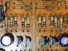
This 771 exhibited random "popping" noise in both channels; measurement of the DC offset at the speaker outputs, demonstrated that the reading would fluctuate widely, reaching at times, several hundred mVs. This behavior was independent of input source and was unaffected by any of the preamp stage controls; suggesting that the problem was in the F-1499 Driver Board. Indeed, the replacement of the stock 2SA640 transistors (TR01-TR04) and the stock DS430 diodes (D01-D04) in the differential input stage eliminated the random "popping" noise. The replacements were hFE-matched KSA992FB pairs and 1N4148 diodes, respectively.
F-1499 TRs Ds.jpg
 
Register to hide this ad
Part 2: Constant Background Hiss & Hum

With the volume control at minimum, a constant low-level hum and hiss noise in both channels was heard over speakers or headphones; noise is much more intrusive when using headphones. During loud playback levels, the noise is apparent during the "silence" between music tracks, and is independent of input source. Unlike the the "popping" noise/fluctuating DC offset issue, this noise issue was affected by the preamp controls, e.g., the -20dB muting switch makes the noise virtually inaudible with the volume at minimum. This behavior suggests that the noise originates in the preamp stage and is amplified by the power amplifier stage.

A quick online search reveals that this 771 hum and hiss issue is not uncommon; further, owners of other models in this series (e.g., 661 and 881) have also reported similar noise issues. The consensus seem to be that this series is plagued by poor implementation of signal/power supply grounding. AK's @ConradH has an excellent article on 881 grounding issues: https://conradhoffman.com/Sansui_881_mods.htm . In the Sansui xx1 receiver line, the grounds are via multiple board solder pads that make contact to the chassis via the screws that secure the boards. It has been reported that cleaning these contact points and tightening the screws can eliminated the hum noise, see https://audiokarma.org/forums/index...um-solved-by-loosening-bottom-screws.1072188/ . Others have soldered additional ground wires to address the hum noise, https://audiokarma.org/forums/index.php?threads/sansui-661-hum-problem.938239/page-5 . Unfortunately, for this 771, cleaning the board grounds and adding additional ground wires only slightly reduced (if at all) the hum noise and the hiss noise was not affected. The solution lies elsewhere...

Addtional Ground Wires.jpg
 
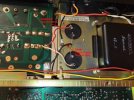
Fun fun! I have to believe when these units were built that grounding was well understood. Otherwise, there would have been no low noise electronics, like test equipment! Why they didn't get it right in audio equipment I can't imagine. It's hard to see in that photo, but how does the transformer center tap get connected to the capacitors? That wire will have a lot of ripple on it and it has to go directly to the caps. Everything else can then come off that center point between the caps. But you know all this, and I bet you're messing with it right now!
 
Oh, yes! Like a dog chasing his own tail, seems like fun at first, but it can get tiring...

It's hard to see in that photo, but how does the transformer center tap get connected to the capacitors? That wire will have a lot of ripple on it and it has to go directly to the caps. Everything else can then come off that center point between the caps. But you know all this, and I bet you're messing with it right now!
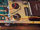
In the stock configuration, the transformer center tap is connected to power supply board at a chassis grounding point, and there are individual ground wires from the main filter capacitors to this point; this is a similar arrangement to that in the 881. Among the many different ground configurations evaluated, a direct connection of the transformer centre tap wire to the centre point between the main capacitors with a single wire connection to the board was not found to make an audible or measurable difference with respect to the hum noise. The new connection between the main capacitors was retained, but the transformer centre tap wire connection was returned to the board, as moving it didn't make much difference.

Stock transformer centre connection.jpg
 
Part 2: Constant Background Hiss & Hum (Conclusion)

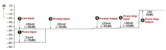
Recalling that the background hum and hiss noise was essentially absent with activation of the -20dB muting switch, it was postulated that a reduction in the preamplifier stage gain might resolve the the noise issue. However, according to the Level Diagram in the 771 Service Manual, the preamplifer stage is essential a unity gain circuit as it only provides 2dB of signal gain. And hence, unfortunately, the 771 preamp stage does not offer any opportunity to address the noise issue.

771 gain schematic.jpg

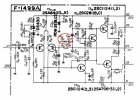
However, the Level Diagram also shows that the power amplifier stage was designed to provide unusually high gain, approximately 43dB. On the F-1499 Driver Board, the resistors, R21/R22 (100kohm) and R25/R26 (470ohm) form the feedback loop voltage divider; with these values the calculated gain is 46.6dB (a bit higher than is listed in the Level Diagram). And, although not shown in the 771 Schematic, the F-1499 board has additional feedback components at R23/R24 (10kohm) and C07/C08 (10pF) for very high frequencies (e.g., >1.6MHz). This extra feedback arm lowers the gain to 26.2dB for MHz frequencies; the corrected schematic is shown below (the additional feedback components are circled).

771 corrected feedback.jpg

The high gain in the power amplifier stage does afford an opportunity to possibly address the 771 noise issues. By installing 47kohm resistors and 1.2kohm resistors at R21/R22 and R25/R26, respectively, the power amplifier gain is lowered to a more typical 32.1dB. For comparison, the power amplifier stage in the AU-7500 integrated amplifier, has a gain of 28.7dB. And, now (drum roll, please), with this modification to the feedback loop, the excessive background hum noise and the hiss noise have been eradicated!

F1499 FB detail label.jpg

Also, note that extra feedback components at R23/R24 and C07/C08 have been removed. Failure to remove these components when R25/R26 is increased to 1.2kohm will cause the amplifier stage to become unstable and oscillate. Interestingly, Sansui discontinued the use of these additional feedback components in the subsequent generations of receivers and amplifiers.
 
Last edited:
Part 2: Constant Background Hiss & Hum (Conclusion)

Recalling that the background hum and hiss noise was essentially absent with activation of the -20dB muting switch, it was postulated that a reduction in the preamplifier stage gain might resolve the the noise issue. However, according to the Level Diagram in the 771 Service Manual, the preamplifer stage is essential a unity gain circuit as it only provides 2dB of signal gain. And hence, unfortunately, the 771 preamp stage does not offer any opportunity to address the noise issue.

View attachment 3564547

However, the Level Diagram also shows that the power amplifier stage was designed to provide unusually high gain, approximately 43dB. On the F-1499 Driver Board, the resistors, R21/R22 (100kohm) and R25/R26 (470ohm) form the feedback loop voltage divider; with these values the calculated gain is 46.6dB (a bit higher than is listed in the Level Diagram). And, although not shown in the 771 Schematic, the F-1499 board has additional feedback components at R23/R24 (10kohm) and C07/C08 (10pF) for very high frequencies (e.g., >1.6MHz). This extra feedback arm lowers the gain to 26.2dB for MHz frequencies; the corrected schematic is shown below (the additional feedback components are circled).

View attachment 3564552

The high gain in the power amplifier stage does afford an opportunity to possibly address the 771 noise issues. By installing 47kohm resistors and 1.2kohm resistors at R21/R22 and R25/R26, respectively, the power amplifier gain is lowered to a more typical 32.1dB. For comparison, the power amplifier stage in the AU-7500 integrated amplifier, has a gain of 28.7dB. And, now (drum roll, please), with this modification to the feedback loop, the excessive background hum noise and the hiss noise have been eradicated!

View attachment 3564558

Also, note that extra feedback components at R23/R24 and C07/C08 have been removed. Failure to remove these components when R25/R26 is increased to 1.2kohm will cause the amplifier stage to become unstable and oscillate. Interestingly, Sansui discontinued the use of these additional feedback components in the subsequent generations of receivers and amplifiers.
Above & beyond the call of duty! I think you have a noise advantage with the 771 as it doesn't use those goofy SIP "op-amps" that really aren't and are difficult to sub with anything else. The 771 is good 'ol discrete transistors. Great job!
 
Is this also relevant for the Sansui 661?

Also, with removing C07/08 and R23/24, do you need to install jumpers, or no?
 
Is this also relevant for the Sansui 661?

Also, with removing C07/08 and R23/24, do you need to install jumpers, or no?
Since the 661, according to its Service Manual, uses the same F-1499 Driver Board and has the same stock feedback resistors, the feedback loop mod described herein can also be applied to it. Jumpers are NOT installed in R23/24 and C07/C08; jumpers would feedback 100% of the signal and result in zero net sound output.
 
Outstanding!
Out of curiosity, what effect did that have on actual measured output power?
The lowering of the power amp stage gain via the feedback loop modification does not affect the maximum power output; this is dependent on the power supply B+ and B- voltages (which are unaffected by the feedback modification). However, the lower gain does impact the power amplifier input sensitivity, i.e., the signal voltage required to drive the power amplifier to full output is now higher following the feedback modification. In use, it means that the volume knob has to rotated a bit more clockwise than before for the same sound loudness. This is actually beneficial since it means that the practical working range of the volume control is now in the rotation range with better inter-channel matching.
 
The lowering of the power amp stage gain via the feedback loop modification does not affect the maximum power output; this is dependent on the power supply B+ and B- voltages (which are unaffected by the feedback modification). However, the lower gain does impact the power amplifier input sensitivity, i.e., the signal voltage required to drive the power amplifier to full output is now higher following the feedback modification. In use, it means that the volume knob has to rotated a bit more clockwise than before for the same sound loudness. This is actually beneficial since it means that the practical working range of the volume control is now in the rotation range with better inter-channel matching.

That's exactly what I was wondering, why did Sansui do this in the first place. It appears to get that quick response with the volume at say 10am. The owner would note that with just a little volume control it was so "loud". When in reality they would have been better off with more actual volume control. That seems to be a theme in vintage audio, front loading the volume control. The mod is worth it for just having a more logical volume control alone. Taming Hiss and Hum of course is more important here, but still a great tweek.
 
That's exactly what I was wondering, why did Sansui do this in the first place. It appears to get that quick response with the volume at say 10am. The owner would note that with just a little volume control it was so "loud". When in reality they would have been better off with more actual volume control. That seems to be a theme in vintage audio, front loading the volume control. The mod is worth it for just having a more logical volume control alone. Taming Hiss and Hum of course is more important here, but still a great tweek.
This is a great observation - I've wondered the same. It made folks go "wow - it is so loud at 10 o'clock - this thing has power", when in fact at 11 o'clock, it would be tapped out and distortion mount.

@Leestereo you solved it! As long as I can remember, I've heard about these hum issues on the xx1's. Huge contribution there :rockon:
 
I agree with @Warren-Oates and @stereofun; having the sound level "loud" early in a volume control's rotation range is definitely a selling advantage in the showroom. And the standard practice of having the "0 dB" notation at the end of the volume control's rotation only reinforces the impression of lots of power reserve. Interestingly, I do have a Sherwood receiver that doesn’t follow this labeling convention, but the volume control does behave "normally".

S-8300 volume control.jpg

Also, its been previously reported that the Sansui AU-9900 did have a "better" usable volume control range, but presumably this "improvement" was not well received (https://audiokarma.org/forums/index.php?threads/sansui-volume-controls.609289/post-8045114): "...my AU 9900 has a volume pot that requires the unit to be turned up way past what is typical of my other Sansui units...enough so that I thought it was malfunctioning. The AU 9900a variant fixed that issue, as customers did not like that pot."
 
Last edited:
I agree with @Warren-Oates and @stereofun; having the sound level "loud" early in a volume control's rotation range is definitely a selling advantage in the showroom. And the standard practice of having the "0 dB" notation at the end of the volume control's rotation only reinforces the impression of lots of power reserve. Interestingly, I do have a Sherwood receiver that doesn’t follow this labeling convention, but the volume control does behave "normally".

View attachment 3568927

Also, its been previously reported that the Sansui AU-9900 did have a "better" usable volume control range, but presumably this "improvement" was not well received (https://audiokarma.org/forums/index.php?threads/sansui-volume-controls.609289/post-8045114): "...my AU 9900 has a volume pot that requires the unit to be turned up way past what is typical of my other Sansui units...enough so that I thought it was malfunctioning. The AU 9900a variant fixed that issue, as customers did not like that pot."
Yes, and interesting that the “issue” with the AU-9900 volume pot was described as being “fixed” in the 9900A. Agree with your observation that the “linear” volume pot must not have been well-received. Both the Professional and Definition series had linear volume pots. Recently, some one here was servicing an AU-20000 and thought something was wrong with it because he had to turn the volume pot ”way up” to get the same loudness as on other amps. I had to explain the difference in the volume pot on the 20000 vs. all other amps.
For me, I absolutely love the volume control on my AU-9900 an the multiple levels of “muting“ it has.
 
Part 3: Baxandall Diode & Capacitors for Driver Board

Since the 771 has a quasi-complementary output stage, the addition of a Baxandall Diode will result in a better distortion profile as it mimics the fully complementary output topology. This modification consists of replacing the 4.7ohm resistors at R45/46 with 220ohm resistors and adding 1N4148 diodes in parallel (cathodes towards the emitters of TR. 11/12). The diodes were installed on the board's solder side. Also, as the Baxandall diode mod will also affect the usable working range of the bias trimmers (VR03/VR04), replacing the stock 1.5kohm resistors at R35/36 with 1kohm ones will restore it.

An additional modification was the installation of film capacitors (1.0µF/100V) across the emitter and collector of the Vbe multiplier transistors (TR07/08) on the solder side of the board. This by-pass capacitor yields better high frequency performance (by improving the voltage regulation across the Vbe transistor at high frequencies). Also installed on the solder side are capacitors that parallel the zener diodes; they lower the zener generated noise.

Note that the aforementioned modifications are completely reversible (e.g., no board traces are cut), should one want to undo them. More details regarding the Baxandall Diode and Vbe Multiplier By-pass Capacitor modifications can found here: https://audiokarma.org/forums/index...rade-of-a-sansui-au-555a.816754/post-11495731

The replacements for the following capacitors were notably different from the stock ones: the input capacitors at C01/02 were upgraded to 1uF film types; the input low-pass capacitors at C03/04 were upgraded to 47pF C0G types; the feedback high-pass capacitors at C05/06 were replaced with 100uF bi-polar types; the bootstrap capacitors at C09/10 were increased to 47uF.

F1499 restored label.jpg

F1499 solder side label.jpg
 
Part 4 : Regulated Power Supply & Protection Circuits

The regulated power supply circuit on the F-1500 board outputs 13.6VDC (to the AM/FM tuner stage) and 33.0VDC (to the phono and preamp stages). During production, Sansui made several modifications to this circuit: R01 was increased to 330ohm; R04 was removed, and instead a 4.7kohm resistor was installed on the solder side to bridge C02 and C05; ZD02 was also moved to the solder side to allow a proper ground connection. The corrected schematic for the regulated power supply circuit is shown below.

771 reg ps corrected.jpg

As this circuit dissipates a significant amount of heat, it is advisable that this be taken into consideration when choosing replacement components. Accordingly, the replacement capacitors are rated at 105°C and have a as small as possible footprint (to improve air circulation). Also, to facilitate heat dissipation in this circuit, the plastic sleeve on TR05 (insulates collector) was removed and a heatsink was installed on TR06.

The protection circuit is located adjacent to the regulated power supply. At power on, the 771 relay typically closes almost immediately (under 2 seconds). This delay is too brief to allow the amplifier DC offset to stabilize sufficiently to avoid a turn-on "pop" noise to be heard. The relay closing delay interval was extended to ~4 seconds by increasing the values of C07, C08 and R07 to 100uF, 470uF and 100kohm, respectively.

771 reg ps restored.jpg

reg ps solder side.jpg
 
Back
Top Bottom