• The move to the new server is done. There are some software and database maintenance updates in process. This has us passing the hat around to help out. We appreciate any donations. Seriously, even a dollar helps. The payment page may be found here - https://www.audiokarma.org/support.html

Leestereo Mods, Tweaks and Tips for the Sansui 771

@Leestereo since I had a 771 on the bench for restoration and service, I decided to try some of these things. I had already performed a full recap, cleaning, tuner alignment, bulb conversion, replacing noisy transistors, etc. The two remaining issues that bothered me were the hiss/noise (even after all problematic and noisy transistors were gone) and the speaker relay engaging too quickly.

The gain modification absolutely eliminates the hiss/noise, and gives better usable range to the volume potentiometer. The pot on mine tracks pretty poorly between channels at the low end, but now thats not an issue since at low listening levels its up around 2-3.

I definitely need to increase the turn-on delay for the relay. It clicks in almost instantaneously and you can hear a huge pop in the speakers because the DC offset has not had nearly enough time to settle down. I will report back but I suspect that will be solved as well.
 
One other note on the xx1 Sansui receivers, or at least on the 881 I was tinkering with the other day. There is another design flaw in that the output zobel is located on the speaker switch, sky wired a foot and a half from the amp output itself. It is not connected to the amp outputs when the relay is open, instead, bizarrely, Sansui grounds the amp outputs via the NC contacts on the relay.
On the unit I was working on, I moved the zobel to the speaker relay and wired it so that it is always connected to the amp outputs, and I also cut off the NC pins, which eliminated a very noticeable power on noise.
 
Part 5: Unregulated Power Circuit

The 771 uses a pair of 10DC-1 and 10DC-R diode modules in the unregulated power supply. As the F-1500 board design allows for the substitution of individual diodes, a worthwhile upgrade is the installation of low-noise soft-recovery types. The replacement diodes should be rated at for at least 3A, 100V PIV to meet the specifications of the stock ones; Vishay BYV28-200 diodes were installed in this 771. Also, note that ceramic capacitor C01 was relocated to the D01 location.

771 diodes.jpg

On the F-1500, the 1uF capacitors at C21/22 decouple the power supply B- rail voltage at the F-1499 Driver Board socket. These capacitors were replaced with 22uF 50V low ESR capacitors. Additional 22uF 50V capacitors were installed on the solder side of the socket to decouple the power supply B+ rail voltage. These decoupling capacitors are necessary to counteract the parasitic inductance of the long traces on the F-1500 board between the power supply and the Driver Board socket.

771 B+ decoupling.jpg
 
I can confirm that the relay-delay modification works exactly as we want. Its about 4 seconds now, and I do not hear any of the pop that I heard when the delay was too short. It feels correct. It's long enough to make sure the output is reasonably stable. If it was too much longer I'd be wondering if something is wrong. Thanks Leestereo!
 
The protection circuit is located adjacent to the regulated power supply. At power on, the 771 relay typically closes almost immediately (under 2 seconds). This delay is too brief to allow the amplifier DC offset to stabilize sufficiently to avoid a turn-on "pop" noise to be heard. The relay closing delay interval was extended to ~4 seconds by increasing the values of C07, C08 and R07 to 100uF, 470uF and 100kohm, respectively.
My 661 has no turn-on "pop" , do I need to extend the delay interval? All other were upgraded following your posts. Thank you so much.
 
Part 6: Equalizer Unit (Phono Stage)

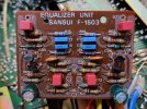
The 771 phono stage (F-1503 board) is a four transistor design that is used in many Sansui receivers and amplifiers. It is generally accepted that the stock 2SC1313 transistors be replaced as they are known to be failure-prone as they age; replacements were KSC1845F transistors (hFE ~400). The input and output capacitors were upgraded to 1.0uF WIMA stacked film types (affords lower leakage and lower distortion). The stock 100uF emitter bypass capacitors were replaced with 330uF capacitors; this increased capacity extends their function to the lower limit of the desired passband, i.e., <20Hz.

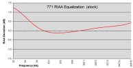
In its stock form, the 771 phono stage has a RIAA equalization error at 3180µs (50.5Hz) that is similar, although not as severe, to that previously noted for the AU-9500 (see Sansui AU-9500: Phono Stage RIAA Equalization Error for details). As can be seen in the graph below, there is a rising bass response beginning at ~120Hz which reaches +1.3dB at 20Hz.

771 riaa stock.JPG

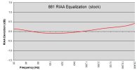
This RIAA error was corrected by replacing the 390kohm resistors at R15/R16 with 332kohm 1% metal film resistors. Interestingly, the RIAA equalization components in the the Sansui 881 phono stage are identical to that used in the 771 except for the use of 330kohm resistors for the 3180µs (50.5Hz) transition. Not surprising, the stock 881 phono stage is consequently more accurate than that seen with the stock 771 phono stage.

881 riaa stock.JPG

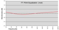
The performance of the 771 phono stage was further enhanced by upgrading the remaining components in the RIAA equalization with higher quality counterparts. The stock 27kohm carbon film resistors at R17/R18 were replaced with 27.4kohm 1% metal film types. The stock 820ohm resistors at R07/08 were replaced with 562ohm 1% metal film resistors; this change further improved the accuracy of the RIAA equalization as well modestly increasing the gain by 2dB. The 2.7nF and 10nF polyester film capacitors were upgraded to polypropylene types. The final modified RIAA equalization is accurate ±0.2dB from 20Hz-20kHz.

771 riaa mod.JPG

771 phono restored.jpg

Also, unlike the 881 phono stage, a local power supply decoupling capacitor was not originally specified for the 771 phono stage; hence, it is a worthwhile tweak to install a 47uF 50V capacitor to the solder side of the F-1503 board.

phono decoupling.jpg

Unusually, the stock phono ground decoupling capacitors in the 771 are 1uF 50V electrolytic capacitors; typically, small value ceramic types are specified for this location. The use of ceramic capacitors here is preferred due to their very low leakage; this minimizes the possibility of noise from the phono ground connection. Accordingly, the stock electrolytic capacitors were replaced with 0.1uF ceramic types.

Phono gnd caps stock.jpg

Phono gnd caps restored.jpg
 
Last edited:
Well this is cool. I have a stack of 771’s and a few 881’s in my inventory. I’m going to apply these mods in one and do an A-B for fun.

Thank you Mr. Lee!
 
Part 7: Preamplifier Stage (F1504-1)

As previously discussed in post #7, the background hum and hiss noise issues that plague the 771 (and the 661) models originate in the preamp/tone stage. Hence, the replacement components chosen for the F-1504 board were low-noise types, e.g., film capacitors instead of electrolytic types in the signal path. Also, minimizing the board's susceptibility to parasitic noise was a consideration during its restoration. For example, since large film capacitors can act as antennae and introduce noise into the signal path, the stock 0.22uF input film capacitors at C05/C06 were replaced with physically smaller 0.47uF ones. The higher value of the replacement capacitor decreases phase shift within the passband and the lowers the corner frequency (F3) to ~2Hz. Note, however, that the original 0.22uF value was still acceptable as it gave a F3 of less than 5Hz. The stock coupling electrolytic capacitors at C07/C08, C17/C18 and C23/C24 were upgraded to stacked film types at the same capacitance values, i.e., 3.3uF, 1.0uF and 2.2uF, respectively. The emitter by-pass capacitors (C21/CC22) and the local decoupling capacitors (C608/C609) were replaced with low-leakage types at the same capacity as stock, again to minimize noise. The failure-prone 2SC1313 transistors (TR01/TR02) were replaced with low-noise KSC1815 types.

771 pre restored.jpg

Also, on the solder side of the F-1504-1 board, one can observe a few Sansui factory modifications: 2 cut traces and 2 jumper connections.

F-1504 cut trace.jpg

The corrected F-1504-1 schematic with the aforementioned factory changes.

F1504-1 corrected.jpg
 
Last edited:
Part 8: Tuner Board (F-1517)

Although the 771 service manual lists the tuner board as F-1479D, this particular 771 has the F-1517 board installed. Note that the service information and schematic for the F-1517 board can be found in the QRX-5500A/7500A Service Manual. The restoration of the tuner board only necessitated the replacement of the electrolytic capacitors and one diode. The replacement capacitors were generally of the same capacity and type as the originals except for the local decoupling capacitor (C49) that was increased to 220uF from the stock 100uF value and the FM output capacitors (C57, C58) which were replaced with bi-polar types. The failure prone DS430 diode at D04 was replaced with a 1N4148 type.

771 tuner restored.jpg
 
Question about performance tweaks. Could apply to many 70's units. Is there any benefit to installing a common mode choke with a capacitor at the power entrance? Any benefit to aluminum foil taping the inside of the wood cabinet? The 771 has no interior metal cover, if I recall correctly. I have a few 70s units where the manufacturer did that. It's not the same as encasing individual boards in metal like on a pioneer sx-1250, but might it help? Especially considering how much RFI EMI is in the average house, cell phones routers, remotes, led lights, etc.
 
Question about performance tweaks. Could apply to many 70's units. Is there any benefit to installing a common mode choke with a capacitor at the power entrance? Any benefit to aluminum foil taping the inside of the wood cabinet? The 771 has no interior metal cover, if I recall correctly. I have a few 70s units where the manufacturer did that. It's not the same as encasing individual boards in metal like on a pioneer sx-1250, but might it help? Especially considering how much RFI EMI is in the average house, cell phones routers, remotes, led lights, etc.
If the other mods, like sorting out the grounding and cutting back the gain in the amp section cure the hum to an inaudible level, I don't expect that you would gain anything. I guess it wouldn't hurt anything to foil line the top cover. A lot of new equipment has a ferrite choke on the power cord, so again, it probably wouldn't hurt anything. Not sure it's worth the trouble.
So, I suppose, the answer is try it and see. :dunno:
 
If I had to guess as to why modern equipment often has ferrite chokes on the power chords and "vintage" doesn't, I would say it's probably more to do with modern equipment being more "chip run" than older equipment and therefore more susceptible to issues caused by RF/EM interference.

My Sansui 8080Db runs it's wood case and nary a hint of interference issues, even with the wireless router right behind the next wall....
 
Part 9: Main Power Supply Capacitors and AC Safety Components

The stock main power supply capacitors (C706, C707) were rated at 4700uF/50V and these were upgraded to 10,000uF/50V 105°C capacitors. The 4.7nF (C702) capacitor on the AC primary was replaced with a proper XY safety capacitor. The 4.7nF capacitor (C701) across the power switch was replaced with a more appropriate snubber (0.1uF safety capacitor + 100ohm 0.5W resistor); due to space constraints in the area where the power switch is located, the snubber was installed on the accessory AC outlets instead of the switch itself. Unusually, the resistor (R880) on the neutral line was originally soldered to the ground return of the right channel speaker; it was re-installed to the chassis itself.

771 AC.jpg

771 PS Main Caps.jpg

Also of note is the generously sized power transformer (for comparison, the main capacitors measure a 35mm x 50mm). From the transformer size alone, one might guess that the 771 is rated at ~50 watts per channel (wpc) at 8 ohms rather than the published rating of 32wpc. Actually, it is the 32wpc that is misleading since the service manual level diagram lists the output at 0dB as 19 volts, i.e., 45 wpc (8 ohm). And, in fact, 45wpc is the power rating of tthe"black trim" version of Sansui 771 receiver, the 8010.

771 8010.JPG
Image from
 
Last edited:
Part 10: Out With The Old and In With The New(ish)

The original plan for this 771 was to address the background noise/hiss issues, replace transistors that are known to be problematic as they age and replace the power supply capacitors (and any other capacitor that was suspect). A relatively small and quick project, so I thought. But resolving the background noise/hiss issue took much more time and effort than originally anticipated (isn't that always the case?). But with the noise/issue taken care of, I was able to give the 771 a critical listen and really liked what was heard...so it was decided to give it the "full monty".

771 Old parts 3.jpg

771.jpg
 
Last edited:
Part 11: Listening Impressions (...this one goes to 11...)

Whether listening to LP records, CDs, or FM broadcasts, this restored 771 never failed to impress. I would describe the overall sound as smooth and full-bodied (so like a good cup of joe?). Perhaps a more useful description for Sansui aficionados, is that this mid-70s model's sound signature is closer to that of the "warm" sounding capacitor-coupled models of the early 70s (e.g., AU-555A) than the more detailed/analytical sounding designs of the late 70s (e.g., AU-919). Playing many of the same recordings listed in the post detailing the sound of the 555A (https://audiokarma.org/forums/index...rade-of-a-sansui-au-555a.816754/post-11528778), and comparing listening notes, much of the comments regarding the restored 555A also hold true for this restored 771. That there are strong sound similarities is not surprising when one considers that both are quasi-complentary designs to which the Baxandall diode and Vbe Multiplier Bypass capacitor mods were added.

There are, however, notable sonic differences between the 555A and 771. For one, the bass range on the 771 sounds tighter/faster and more powerful; of course this is afforded by the 771's greater output power (45 wpc vs. 25 wpc) and power reserve (2x 10,000uF main caps), but it is undoubtedly also a product of its direct-coupled output. And as good as the 555A's treble range is, and it is quite good, the 771's is clearer (more articulate). This is possibly due to the overall lower level of high frequency noise in the 771 which results in less masking of the treble range by noise components. A contributing factor to the 771's superior high frequency performance may also be the use of JFETs in the preamp stage; JFETs are considered by some (many?) to mimic triode tube performance. Interestingly, Sansui didn't use JFETs in the series TOTL 881, nor in the subsequent x0x0 series of receivers (both used the BA312 proto IC in their phono and preamp stages). However, Sansui did start implementing JFETs in earnest in the later generation AU-x17 integrated amplifier line and the G-x000 receivers.

Compared to the sound of later generation Sansui, for example, the AU-919 (https://audiokarma.org/forums/index...pgrade-of-a-sansui-au-919.698011/post-9436761). the 771 has a more laid-back or relaxed sonic presentation. It's akin to sitting in near the middle of a concert venue rather than in the first few rows; where the reflected bass and midrange dominates and the treble sounds are more diffuse. My listening notes repeatedly commented on the "richness" of the mid and lower ranges. This is not to say that the high range is lacking detail in absolute terms, but rather that it has a "softer" timbre in comparison to the late generation Sansui sound.

Some of the recordings (CD and LP) used during the listening sessions (in no particular order): Lou Reed/Transformer; Charlie Watts Quintet/Warm & Tender; Steely Dan/Aja; Miles Davis/Kind of Blue; Bach (Gendron)/Cello Suites; Julie London/Julie Is Her Name, Vol. 1 & 2; Dire Straits/Love Over Gold; Eric Clapton/Unplugged; Beatles/Abbey Road; Sarah McLachlan/Surfacing; Mozart (Snitil, Panenka)/Violin and Piano Sonatas; Beethoven (Nishizaki and Jando)/Violin Sonatas No.5 and No. 9; Dave Brubeck/Time Out; ECO (Leppard)/Bach Brandenburg Ctos; Duke Ellington Orchestra/Digital Duke; VPO (Böhm, 1972) Beethoven Symphonies no. 6 & no. 9; NYPO (Bernstein, 1961), Beethoven Symphony no. 5; Wynton Marsalis/Standard Time Vol. 3.

 
Compared to the sound of later generation Sansui, for example, the AU-919 (https://audiokarma.org/forums/index...pgrade-of-a-sansui-au-919.698011/post-9436761). the 771 has a more laid-back or relaxed sonic presentation. It's akin to sitting in near the middle of a concert venue rather than in the first few rows; where the reflected bass and midrange dominates and the treble sounds are more diffuse. My listening notes repeatedly commented on the "richness" of the mid and lower ranges. This is not to say that the high range is lacking detail in absolute terms, but rather that it has a "softer" timbre in comparison to the late generation Sansui sound.
Thanks for this explanation with the rows of a live event! I was always trying to find words to describe this sound characteristic of 881. I was thinking of reverb or spacial information.i like this kind of presentation as being there.
Also , would like to know your thoughts on the phono stage of 881 /771 in comparison to modern stand alone budget phono preamps like rega ,schiit, ifi etc
Thanks
 
Back
Top Bottom