Leestereo
Super Member
Have the DS430 diodes on F-1499 been replaced?OK, small update. I replaced the differential transistors with the new pairs. DC voltage still fluctuates.


Have the DS430 diodes on F-1499 been replaced?OK, small update. I replaced the differential transistors with the new pairs. DC voltage still fluctuates.
Yes, I used 1N4148 as recommended.Have the DS430 diodes on F-1499 been replaced?
Update: Hum has been elimminated. Found a ground loop (created during previous attempts of fixing the 771 "illness"). After that, DC offset value stabilised (fluctuations of a few mV), and I was able to set it as low as possible.Yes, I used 1N4148 as recommended.


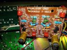


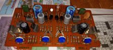
On the F1517 tuner board, C49 is the local decoupling/filtering capacitor for the regulated power supply input of 13V and should be 100uF/16V.2) tuner board cap c49 had a .1uf. Lee suggested increasing it from 100uf to 220uf. I'm not sure about this.
3) c701 pwr switch cap replacement was placed in same spot with 100ohm resistor. unsure of placement of resistor- which side.
5) tone board pots (rear section)have no holes to add deoxit

Presumably, some early manufactured 771s had the F-1487d tuner board, but it may be that most 771s have the F-1517 board.it's the schematic. i'm looking at board f-1479d for the tuner- c49= .1uf/ 25v on the schem I have. sansui strikes again! just thought it a dramatic jump in uf. checked, and had replaced it with 220uf.
did spay doxit fader under the legs- wasn't sure if it was open.
stereo separation is definitely clear. lots and lots of bass and treble. have treble set below half and bass at zero. might just blow a spkr- lots of pwr.
thanks leestereo.

Do the higher capacitance filter caps create any issues for the stock rectifier diodes as far as any increased inrush current? Newb here so just asking?Part 9: Main Power Supply Capacitors and AC Safety Components
The stock main power supply capacitors (C706, C707) were rated at 4700uF/50V and these were upgraded to 10,000uF/50V 105°C capacitors. The 4.7nF (C702) capacitor on the AC primary was replaced with a proper XY safety capacitor. The 4.7nF capacitor (C701) across the power switch was replaced with a more appropriate snubber (0.1uF safety capacitor + 100ohm 0.5W resistor); due to space constraints in the area where the power switch is located, the snubber was installed on the accessory AC outlets instead of the switch itself. Unusually, the resistor (R880) on the neutral line was originally soldered to the ground return of the right channel speaker; it was re-installed to the chassis itself.
View attachment 3604854
View attachment 3603884
Also of note is the generously sized power transformer (for comparison, the main capacitors measure a 35mm x 50mm). From the transformer size alone, one might guess that the 771 is rated at ~50 watts per channel (wpc) at 8 ohms rather than the published rating of 33wpc. Actually, it is the 32wpc that is misleading since the service manual level diagram lists the output at 0dB as 19 volts, i.e., 45 wpc (8 ohm). And, in fact, 45wpc is the power rating of tthe"black trim" version of Sansui 771 receiver, the 8010.
View attachment 3604306
Image from
Part 5: Unregulated Power Circuit
The 771 uses a pair of 10DC-1 and 10DC-R diode modules in the unregulated power supply. As the F-1500 board design allows for the substitution of individual diodes, a worthwhile upgrade is the installation of low-noise soft-recovery types. The replacement diodes should be rated at for at least 3A, 100V PIV to meet the specifications of the stock ones; Vishay BYV28-200 diodes were installed in this 771. Also, note that ceramic capacitor C01 was relocated to the D01 location.
View attachment 3573901
On the F-1500, the 1uF capacitors at C21/22 decouple the power supply B- rail voltage at the F-1499 Driver Board socket. These capacitors were replaced with 22uF 50V low ESR capacitors. Additional 22uF 50V capacitors were installed on the solder side of the socket to decouple the power supply B+ rail voltage. These decoupling capacitors are necessary to counteract the parasitic inductance of the long traces on the F-1500 board between the power supply and the Driver Board socket.
View attachment 3573910
Thanks. Missed that.LeeStereo suggested they be replaced:
Apart from cleaning repeatedly all pots and replacing known noisy transistors and old caps, I don't know. The one I've done this mod to is dead quiet. I'm still tuning it,in respect to caps or trying to refine the sound. New caps are not what they're suppose to be- a 10uf reads 9400, etc.- a 12 or 13uf sounds better to me. Those wires on the tone board eventually break, adding to the complications. Can't take enough pics.Thursday night I finished up my first 661 restore and only my second restore I've finished. Looked good on the O scope so I connected to speakers and was pretty disappointed when I found a pretty annoying occasional pop with the on off switch and a hum/hiss. I though for sure I had mucked something up.
Yesterday doomscrolling Facebook there was a post in a vintage forum that led me to this thread. What a relief! I can't wait to try the speaker relay delay mod.
I do have one question. My hum is noticeably louder in the right channel speaker output. It is present on all sources at minimum volume. I didn't replace the diodes in the driver board or PS board, so I will go ahead and do those since I have them. Should I be looking at anything in particular in the right channel?




There are two pairs of modules in my Sansui, 2x 10DC-1, 2x10DC-R, does the modification mean removing these four modules and replacing them with only four diodes?Part 5: Unregulated Power Circuit
The 771 uses a pair of 10DC-1 and 10DC-R diode modules in the unregulated power supply. As the F-1500 board design allows for the substitution of individual diodes, a worthwhile upgrade is the installation of low-noise soft-recovery types. The replacement diodes should be rated at for at least 3A, 100V PIV to meet the specifications of the stock ones; Vishay BYV28-200 diodes were installed in this 771. Also, note that ceramic capacitor C01 was relocated to the D01 location.
View attachment 3573901
On the F-1500, the 1uF capacitors at C21/22 decouple the power supply B- rail voltage at the F-1499 Driver Board socket. These capacitors were replaced with 22uF 50V low ESR capacitors. Additional 22uF 50V capacitors were installed on the solder side of the socket to decouple the power supply B+ rail voltage. These decoupling capacitors are necessary to counteract the parasitic inductance of the long traces on the F-1500 board between the power supply and the Driver Board socket.
View attachment 3573910
Yes, that is correct (see picture shown in post no. 25).There are two pairs of modules in my Sansui, 2x 10DC-1, 2x10DC-R, does the modification mean removing these four modules and replacing them with only four diodes?