Part 4 : Regulated Power Supply & Protection Circuits
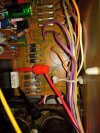
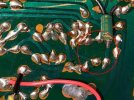
The regulated power supply circuit on the F-1500 board outputs 13.6VDC (to the AM/FM tuner stage) and 33.0VDC (to the phono and preamp stages). During production, Sansui made several modifications to this circuit: R01 was increased to 330ohm; R04 was removed, and instead a 4.7kohm resistor was installed on the solder side to bridge C02 and C05; ZD02 was also moved to the solder side to allow a proper ground connection. The corrected schematic for the regulated power supply circuit is shown below.
View attachment 3570848
As this circuit dissipates a significant amount of heat, it is advisable that this be taken into consideration when choosing replacement components. Accordingly, the replacement capacitors are rated at 105°C and have a as small as possible footprint (to improve air circulation). Also, to facilitate heat dissipation in this circuit, the plastic sleeve on TR05 (insulates collector) was removed and a heatsink was installed on TR06.
The protection circuit is located adjacent to the regulated power supply. At power on, the 771 relay typically closes almost immediately (under 2 seconds). This delay is too brief to allow the amplifier DC offset to stabilize sufficiently to avoid a turn-on "pop" noise to be heard. The relay closing delay interval was extended to ~4 seconds by increasing the values of C07, C08 and R07 to 100uF, 470uF and 100kohm, respectively.
View attachment 3570860
View attachment 3570890