• The move to the new server is done. There are some software and database maintenance updates in process. This has us passing the hat around to help out. We appreciate any donations. Seriously, even a dollar helps. The payment page may be found here - https://www.audiokarma.org/support.html

Little Bear Tube Phono Pre??

Been following this, as I had purchased a couple of the Little Bear pre-amps some time back. Recently purchased the SS Phono pre, but also purchased the 3-tube pre amp AND the Tube Phone Pre. So, those 3 items have yet to arrive....but when they do, I can see I'm going to have my work cut out for me. I'm a bit suspicious of the stock PT.....and wouldn't doubt at all that mine will come with some 'out of spec' voltages being supplied. So, I too will want to see that diode mod, and I will be sure to check the grounding on pin 9 of the driver tubes. I think I will also look for a small 'project' box to mount this thing in. Seems the exposed circuitry with the high gain makes for a problem in practical application. Anyway, good thread...good info....and will be interesting to see if the folks in China end up producing a metal box for this themselves. Cheers! Tom D.
 
Well I checked this 3 times, and measured with my Fluke 88 in DC, my 15v was 11.2v, and my 6.3 was 24.5v. Can this be right? My 87 gave the same reading. Automotive meters to be sure, but they have been trustworthy in the past.
 
Ugh!!! Perhaps these PTs are the 'Achilles' Heel' of these units?
 
Well I checked this 3 times, and measured with my Fluke 88 in DC, my 15v was 11.2v, and my 6.3 was 24.5v. Can this be right? My 87 gave the same reading. Automotive meters to be sure, but they have been trustworthy in the past.

Check again...Use the AC setting on the Meter...
 
Did that in case you asked! Values are for left and right each block. Line voltage was 122v.
15V 10.6/10.6
6.3V 4.7/9.9
 
Sled, I noticed in the pic you have posted of your amp that the PT is shown to be a 220V unit. Did you have any discussion with the provider of the unit as to why that denotation is present yet you're using it here in the US on 117VAC? I see a LOT of these Chinese units are designated as being either 110 or 220 volt units, but they also state that they will supply a 'proper' transformer based on ship-to location. I'm just curious about this.....although seems a 220V PT would be giving you 'less' voltage.....not more. So....now I'm even more confused...... WC
 
The Pics that I posted where from the Listing...The one that I have is for 110V Input...
And Jimerson...How did you get 2 Voltages at the Blocks? See what you get from Both Sides together, not from Each to Ground...
 
Roger that. I thought it was strange to get 2 different readings, but there it is. That only happened in AC. I'll check tonight. BTW, thanks for your help.
 
So...can someone tell me if I drop this into a top less metal box could I simply solder a ground wire from the board to the box? Sounds like a cheap enough fix if that's all it takes.

And...how about damping sheet on the PT?
 
What about running a ground wire to the PT cover? Looks to me like the PT is mounted on a plastic sheet......so the 'natural' ground the PT would normally get by being mounted on the metal chassis is non-existent. I'm thinking a ground wire ought to be run to the PT cover/case as well? Yes/No? WC
 
Good morning. My readings for the 6.3v was 7.3, for 15v was 18.3. I listened to this last night for about an hour, and despite the high gain/hum, it sounded pretty freakin' good. For the money, I think it's worth messing with, and I could learn something (like how to measure voltage, har har).
 
Good morning. I listened to this last night for about an hour, and despite the high gain/hum, it sounded pretty freakin' good. For the money, I think it's worth messing with, and I could learn something (like how to measure voltage, har har).

Agreed ;)
 
Those are the same Voltages as I had...Now, the Fun Begins. You will need (10) 1.5A 100V Diodes. Larger Ones will work, but they'll be Harder to work with. (2) In to Outs will go on One Input to the 6.3V Block, and (4) in Series need to go on Each the 15V Inputs to the Block.

attachment.php
 

Attachments

  • Little Bear Diodes.jpg
    Little Bear Diodes.jpg
    71.1 KB · Views: 1,154
Hey thanks for the handy pic, Mr Sled . I can do that. That looks parallel, but when you reverse one of the 2 diodes that makes it series, right? (did that make sense?)
 
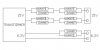
Each is a Pair in Parallel, In to Out...(1) Pair on the 6.3V... (2) Pair in Series on Each of the 15V.
 
Sled, can you do that in 'schematic' form? I'm still looking at the pics and just not seeing what you're saying. Further, I'm seeing 6 of one type diode and 4 of another. Will your typical 1N4007s work for this? I think I just bought a hundred of those for use on tube rectifier sockets as 'arc' protectors. But, while this looks easy enough, I'd still like to see the circuit drawn out just so I get the polarity correct.

Thanks, Tom D.
 
The 1A 1n4007's can easily be used for the 6.3V. It will be cutting it Close using them on the 15V. I used (4) of them along with the only (4) 4A ones that I had...
attachment.php
 

Attachments

  • Little Bear Diode Schem.JPG
    Little Bear Diode Schem.JPG
    21.4 KB · Views: 1,112
Sled, VERY nicely done on the schematic version! Wish I had that talent!

One more quick question: I'm unfamiliar with the aspect of this that would require this 15 volt circuit? I get the 200 volts as a 'B+' feed, and the 6 volts for heater voltage, but just what is the 15 volts for? WC
 
, never saw this thread, but just bought 3 little bear preamp / headphione jobs. I bought them mostly for some technology. I didn't get the RIAA job because I'm addicted to MC.
 
Back
Top Bottom