• The move to the new server is done. There are some software and database maintenance updates in process. This has us passing the hat around to help out. We appreciate any donations. Seriously, even a dollar helps. The payment page may be found here - https://www.audiokarma.org/support.html

Marantz 2230 Transformer

It looks like there are only three filter caps on the P400 board, C405 (10uF), C406 (10uF), C409 (100uF). The rest are bypass caps. Does touching it affect only one channel (L or R), or both?

It looks like there are only three filter caps on the P400 board, C405 (10uF), C406 (10uF), C409 (100uF). The rest are bypass caps. Does touching it affect only one channel (L or R), or both?
Hey, yes it only affects the left channel, weird thing is that since I touched it the hum is gone by about 70%. I believe I have at least 2 issues. One being the hum noise and the second is the right channel is has very low output. I’m basically trying to rule out the transformer before I spend to much time and money on this because a replacement transformer is looking like it’s next to impossible to be found? Do you know how I can attach a video from an iPhone? I can attach pictures but not sure about the video? I have a video of the hum while touching the cap.
 
Warning: If this is too complicated for you, don't risk damaging your receiver or yourself. Take it to a technician.

OK, let's check the power supply voltages first to make sure they are OK.
I am assuming that you have a Digital Multimeter (DMM) and know how to use it.

CAUTION: There are high voltages present in the chassis and boards where we will be looking. Use caution when touching wires, board traces, and components because some will have AC line voltage on them.
  1. Power OFF
  2. Find the P800 Power Supply board
  3. Set the DMM to measure DCV
  4. Clip the black lead to terminal J802 GND
  5. Clip the red lead to terminal J808 35.6V
  6. Turn on power
  7. What do you measure?
  8. Next, move the red lead to terminal J805 14V
  9. What do you measure?
1789738581349.png1789738607128.png

Next, there are two Power Amplifier (P750) boards, one for the L channel and one for the R channel.
Measure both boards.
  1. Power OFF
  2. DMM to measure DCV
  3. Find the left channel P750 board
  4. Clip the black lead to J752 ground
  5. Clip the red lead to J754 +66.5V
  6. Turn on power
  7. What do you measure for the L and R boards?
  8. Turn off power
1789738879153.png
1789738911237.png
 
I believe I have at least 2 issues. One being the hum noise and the second is the right channel is has very low output.
You can isolate the low output issue to the Preamp or Main amp.
  • Remove the Preout to Main In jumpers on the back of the receiver
  • Use a short stereo RCA cable to cross-connect the L Preout to R Main In and R Preout to L Main In.
  • Does the hum remain on the same side?
  • Does the low output remain on the same side?
 
  • Like
Reactions: mbz
Warning: If this is too complicated for you, don't risk damaging your receiver or yourself. Take it to a technician.

OK, let's check the power supply voltages first to make sure they are OK.
I am assuming that you have a Digital Multimeter (DMM) and know how to use it.

CAUTION: There are high voltages present in the chassis and boards where we will be looking. Use caution when touching wires, board traces, and components because some will have AC line voltage on them.
  1. Power OFF
  2. Find the P800 Power Supply board
  3. Set the DMM to measure DCV
  4. Clip the black lead to terminal J802 GND
  5. Clip the red lead to terminal J808 35.6V
  6. Turn on power
  7. What do you measure?
  8. Next, move the red lead to terminal J805 14V
  9. What do you measure?
View attachment 3838986View attachment 3838987

Next, there are two Power Amplifier (P750) boards, one for the L channel and one for the R channel.
Measure both boards.
  1. Power OFF
  2. DMM to measure DCV
  3. Find the left channel P750 board
  4. Clip the black lead to J752 ground
  5. Clip the red lead to J754 +66.5V
  6. Turn on power
  7. What do you measure for the L and R boards?
  8. Turn off power
View attachment 3838988
View attachment 3838989

That’s great, I definitely comfortable with a dmm, i’ll try these test tonight or possibly tomorrow.
 
You can isolate the low output issue to the Preamp or Main amp.
  • Remove the Preout to Main In jumpers on the back of the receiver
  • Use a short stereo RCA cable to cross-connect the L Preout to R Main In and R Preout to L Main In.
  • Does the hum remain on the same side?
  • Does the low output remain on the same side?
So I did this the other day and the low channel switched to the left, I’ll try it again this evening because I’m drawing a blank on what happened to the hum! Thanks
 
You can isolate the low output issue to the Preamp or Main amp.
  • Remove the Preout to Main In jumpers on the back of the receiver
  • Use a short stereo RCA cable to cross-connect the L Preout to R Main In and R Preout to L Main In.
  • Does the hum remain on the same side?
  • Does the low output remain on the same side?
Ok sorry for the delay but low output 100% changes side to side when I used the jumper rca cable. The hum although remains on the left channel. The hum goes away 90% when I touch the chassis, but for the life of me I cannot find any ground issues.
 
low output 100% changes side to side when I used the jumper rca cable.
OK, so that means that the low signal level originates somewhere in the Preamp before the jumpers. We'll get to that later.
The hum although remains on the left channel.
The hum then appears to be generated in the Main Amp L channel only. This should be relatively easy to locate.
I would also assume that the hum in the L channel is not affected by the Volume control.
Hum is usually caused by a bad ground somewhere to the board. In this case either from the Main In RCA to the P750 L board or on the board itself.
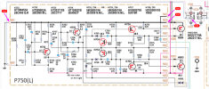
With power off and receiver unplugged from AC we can check the board grounds.
  • Use your DMM set to measure Ohms
  • Clip the black lead to the chassis metal
  • Use the red lead to measure continuity at the 4 places shown on the schematic
  • P750(L) J752
  • P750(L) J763
  • P750(L) J762
  • Main In L channel RCA outer conductor (metal)
  • All should measure close to 0 Ohms
1789839610009.png
1789840108675.png
 
In the previous test, we determined that if you swap PreOut/Main In RCAs the problem moves to the other channel indicating a PreAmp issue.
Let's find the source of the R channel low output.
  1. Is the R channel low for all inputs (AM, FM, Phono, Aux), or only some?
  2. If you push in the Tape Monitor button and connect a source to the Tape In RCA jacks do you still have a low R channel output?
  3. Have you cleaned the Selector rotary switch with Deoxit or contact cleaner?
 
In the previous test, we determined that if you swap PreOut/Main In RCAs the problem moves to the other channel indicating a PreAmp issue.
Let's find the source of the R channel low output.
  1. Is the R channel low for all inputs (AM, FM, Phono, Aux), or only some?
  2. If you push in the Tape Monitor button and connect a source to the Tape In RCA jacks do you still have a low R channel output?
  3. Have you cleaned the Selector rotary switch with Deoxit or contact cleaner?
Right channel low on all inputs yes, just connected a tape deck to the tape in input and push the tape monitor button and the right channel is low for it aswell. As far as the ground checks I have 0 ohms at J752, J762 but no continuity at J763. J763 is a red wire from the left amp to one of the main power supply caps, the largest 4700uf one?
 
Right channel low on all inputs yes, just connected a tape deck to the tape in input and push the tape monitor button and the right channel is low for it aswell. As far as the ground checks I have 0 ohms at J752, J762 but no continuity at J763. J763 is a red wire from the left amp to one of the main power supply caps, the largest 4700uf one?
Oh and I did clean all the switch and controls with deoxit including the selector rotary switch.
 
Warning: If this is too complicated for you, don't risk damaging your receiver or yourself. Take it to a technician.

OK, let's check the power supply voltages first to make sure they are OK.
I am assuming that you have a Digital Multimeter (DMM) and know how to use it.

CAUTION: There are high voltages present in the chassis and boards where we will be looking. Use caution when touching wires, board traces, and components because some will have AC line voltage on them.
  1. Power OFF
  2. Find the P800 Power Supply board
  3. Set the DMM to measure DCV
  4. Clip the black lead to terminal J802 GND
  5. Clip the red lead to terminal J808 35.6V
  6. Turn on power
  7. What do you measure?
  8. Next, move the red lead to terminal J805 14V
  9. What do you measure?
View attachment 3838986View attachment 3838987

Next, there are two Power Amplifier (P750) boards, one for the L channel and one for the R channel.
Measure both boards.
  1. Power OFF
  2. DMM to measure DCV
  3. Find the left channel P750 board
  4. Clip the black lead to J752 ground
  5. Clip the red lead to J754 +66.5V
  6. Turn on power
  7. What do you measure for the L and R boards?
  8. Turn off power
View attachment 3838988
View attachment 3838989
This is great help btw, so for pwr supply voltages I have 34.4v at J808 and 13.3v at J805. And at the amp boards (p750) I’ve got 66.8v at J755 Left and 66.8v at J755 Right.
 
Last edited:
no continuity at J763
Maybe I got the number wrong. I couldn't read it on the board layout. Looks like J763 is all the way to the right.

Can you also check caps C754 & C755. They should be facing the same direction. Some boards had incorrect + markings.

1789845658812.png
 
Maybe I got the number wrong. I couldn't read it on the board layout. Looks like J763 is all the way to the right.

Can you also check caps C754 & C755. They should be facing the same direction. Some boards had incorrect + markings.

View attachment 3839890
They are facing the same direction, as far as testing them do they have to be pulled out of circuit to do a capacitance test with a dmm or can I check them in circuit?
 
For an accurate test you should remove at least one cap leg then test.
What make/model DMM do you have? Does it have capacitance test capability?
So do you have continuity between chassis ground and J763?
 
For an accurate test you should remove at least one cap leg then test.
What make/model DMM do you have? Does it have capacitance test capability?
So do you have continuity between chassis ground and J763?
I just tested J763 and I had high resistance now no continuity?
 
Sorry again. J763 is not the ground. I think you are OK. (Helping too many people and getting confused. :oops:)
 
  • Like
Reactions: mbz
just connected a tape deck to the tape in input and push the tape monitor button and the right channel is low for it aswell.
If you connect the Tape Out RCAs to the tape deck tape in, put the deck in REC-Pause, select source Aux or another input source on the 2230, do both VU meters move at the same level or is one low?
 
Back
Top Bottom