• The move to the new server is done. There are some software and database maintenance updates in process. This has us passing the hat around to help out. We appreciate any donations. Seriously, even a dollar helps. The payment page may be found here - https://www.audiokarma.org/support.html

My first tube amp - Scott LK-72-B

Four 220K resistors are cheap insurance against thermal runaway in these tubes.
Sorry to bug you again Jack, but is 1/2watt ok for the 220K resisitors? Based on the size, it looks like the original 330K are 1/2watt, but I'm not sure.

What a beautiful circuit. Question to those who may know, why is it ok for the two transformers in the build to be aligned in the same direction? Wouldn't that create overlapping magnetic fields, inductance, noise?
I don't know anything about that, but I can tell you the Scott is dead quiet, even in it's current unrestored state and with efficient Altec 604-8G speakers. I have two newer tube amps and have had problems with speaker hum with both of them. One of them is the Rogue Cronus Magnum II which is highly regarded, but the hum is so bad I will probably be selling it once I'm finished upgrading the Scott. I was shocked that the 60-year-old Scott with it's original components could perform better than the Rogue, at least to my ears. And the Rogue's previous owner upgraded all the tubes, which probably cost more the I paid for the Scott.
 
Sorry to bug you again Jack, but is 1/2watt ok for the 220K resisitors? Based on the size, it looks like the original 330K are 1/2watt, but I'm not sure.
Absolutely no problem, if I couldn't help other builders/restorers with things like this, I wouldn't be on the forum. Yes, 1/2W is more than sufficient, electrically speaking. Just be aware that many 1/2W resistors now are really tiny with thin, floppy leads, and they don't work well from the standpoint of installation. Be sure to look up the component body size, lead lengths and lead diameters before ordering. Companies like Digikey have all that available through the datasheet links on the parts pages. Move to 1W for this if you have to, it won't hurt anything.

Jack
 
Absolutely no problem, if I couldn't help other builders/restorers with things like this, I wouldn't be on the forum.
Thanks so much. I couldn't have figured this out without your assistance. I thought choosing capacitors was difficult, but now I'm picking resistors and that's equally confusing. I'm on Mouser and sometimes get dozens of results with specs that almost identical. For most of the resistors I was choosing "Carbon Film Resistors - Through Hole", but then I got to the 1ohm 1% 1watt you recommended and it is only available in either Metal Film or Wirewound.

Does it make any difference? I was going to pick the Wirewound below because it is physically larger with thicker leads, but still smaller than the ones that are in that spot now.


Thanks again,

Andy
 
I usually prefer the 1/2 watt carbon film resistors from Radiodaze.com. The are inexpensive and sound great. Sturdy leads and they measure within decent tolerance
 
... I got to the 1ohm 1% 1watt you recommended and it is only available in either Metal Film or Wirewound.
Any type except carbon composition is good at this low value. Inductance isn't an issue. I would buy the metal film, but be sure to look at their physical characteristics like I mentioned earlier. Actually, if you can wait just a bit, I'll look to see what I used in my last few builds.

Jack
 
Well, I can't retrieve my previous orders online at Digikey for some reason. However, this is what I would use (metal film):

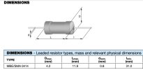
Screen Shot 2025-01-10 at 2.38.43 PM.pngresistor 1 ohm.jpg
Jack
 
Last edited:
Thanks for the resistor info. I think I'm just about done with my parts list. Last decision I have to make is about the can caps. This was discussed earlier in the thread and I was leaning toward the Hayseed Hamfest, but with the current exchange rate on the Canadian dollar those four cans will cost about $300CAD with shipping and tax. Yikes!

So I started looking at the cost to restuff the cans and it's only about $33 for the 12 caps required. That's a big, big difference and adding those caps to my Mouser order puts me over $100 and I'll qualify for free shipping and save the $20 for UPS. So I think I'll try that to start. I can always buy the Hamfest later if I ever decide it's worth it.

Here's what I'm looking at for the cans. Some original values were not available, so I went with the closest higher value. Hamfest also increased some values from the original specs.

C201 Original Specs 2x 20uF/450V & 2x 25uF/25V, replace with 2x Nichicon ULD2W220MHD1TO 22uF/450V & 2x Panasonic EEU-FS1H270B 27uF/50V

C202 & C204 Original 2x 30uF/500V, replace with 2x Nichicon UCY2H330MHD 33uF/500V

C203 Original 4x 100uF/75V, replace with 4x Nichicon UFW2A101MPD 100uF/100V

As always, any feedback is greatly appreciated.

Andy
 
Last edited:
adding those caps to my Mouser order puts me over $100 and I'll qualify for free shipping
For future reference, Digikey ships free if you mail the order and include a check. This is great when you're in the middle of a project and realize you forgot a few resistors or caps.

DigiKey Terms and Conditions
"When a check or money order accompanies your order, DigiKey pays all shipping and insurance via ground service level to all addresses in the U.S. and Canada."

Jack
 
I usually prefer the 1/2 watt carbon film resistors from Radiodaze.com. The are inexpensive and sound great. Sturdy leads and they measure within decent tolerance
Thanks for the suggestion. I had never heard of Radiodaze and like the "'Classic' vintage resistor appearance". Shipping costs to Canada might be too expensive for a few resistors, but I will keep them in mind.

For future reference, Digikey ships free if you mail the order and include a check.
That's good to know. Thanks.
 
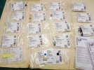
It's taken awhile to get the ball rolling on this, but I finally received my parts today. While reading other threads here I saw the recommendation to add a CL-80 Inrush Current Limiter and a Safety Capacitor to replace the .01uF 10KV capacitor C206. The safety cap recommended was this one which is 400/250V 0.01uF. Not sure how important those two items are, so any feedback is much appreciated.

I decided to go with MPW caps as they were very reasonably priced and I saw them recommended in several forum posts and youtube videos. I was surprised the capacitance value is not marked on them as seen in image below. Is this common with new caps like this? Is it a good idea to write the value on them with a sharpie or something in case I ever need to see the values in the future?

I hope to get started replacing parts tomorrow and will start with the coupling caps and the 1 Ohm cathode resistors. Also thinking I will use the technique shown at the link below. Seems like it might work as well as the hook and loop method someone recommended here earlier, but might also be easier to remove an item if I screw something up. Hopefully that isn't required though.

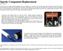
Screen Shot 2025-01-21 at 6.14.17 PM.png
20250121-Scott-LK-72-B-0026.jpg
20250121-Scott-LK-72-B-0027.jpg20250121-Scott-LK-72-B-0025.jpg
 
Last edited:
Hoping someone can clarify a couple questions about setting the DC balance. Do I need to remove the 6U8 tubes? The original manual says to remove tube V3 when adjusting the Left Balance then to replace it and remove V103 when adjusting Right Balance. I also read this post here that describes the balance/bias process and it says "remove the phase inverter tubes (6U8 or others)", which sounds like you remove them all at the same time, rather than one at a time. However, I also read another post at diyaudio with a detailed description of setting balance and bias on the LK72B and it doesn't say anything about removing tubes.

The first link also says to attach a 16ohm resistor to the speaker terminals and measure the voltage across the resistor with the meter set to "AC Volts", but the diyaudio link says to attach speakers or resistors to the speaker terminals and measure the voltage "between the plate connections on the two Power tube sockets" with the meter set to DC volts. Is that just two different ways of achieving the same results, one measuring AC and one DC?

I'm a bit confused, so any advice is appreciated as always.

Thanks.
 
Last edited:
Finally started replacing components. New coupling caps installed last night and I'll be doing the cathode resistors and few other caps today.

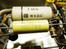
20250125-Scott-LK-72-B-0039.jpg
 
The LK-72B schematic indicates about +460V on the output tube anodes. I would adjust the two bias pots and the DC balance pots for about 30mA at each cathode. That's a total dissipation (plate plus screen) of about 14W at each tube. The original bias test points and the procedure in the manual will no longer be valid, so you'll need to measure the voltage at each cathode.

Jack

Hi Jack,

I hope you might still be available to offer some advice.

I replaced the 0.1uF coupling caps yesterday and today I did the two .047uF near the coupling caps and replaced the 330KΩ grid resistors with 220K as discussed above.

I was about the replace the 2Ω cathode resistors with the 1Ω you recommended, but I thought I would try setting Balance and Bias first to get comfortable with the procedure. I figured if I was aiming for 30-35mV with 1Ω resistors, then I would be shooting for 60-70mV with the 2Ω that are in there now.

I was able to set Balance in both channels to zero no problem, but the highest Bias I could get was 59mV on the Right Channel and about 38mV on the Left Channel.

Am I doing something wrong or could this be an indication of another issue somewhere?

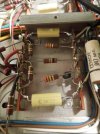
Thanks for any advice. Here's a pic of my work so far.

IMG_0959.JPG
 
Before hunting for an issue in the circuitry, it might be a good idea to swap the right channel and left channel output tubes. Eliminate the possibility that this is the tubes themselves before continuing.

Jack
 
Thanks Jack. I was just looking at it again and was wondering if the tubes might contribute to the low bias. If you recall my early posts and photos, one of the tubes looks like it was overheated and it's in the channel with lowest bias. I will swap the tubes and see what happens.

I also bought another quad of 7591s that tested strong, but wanted to wait until I replaced the coupling caps and I fully understand balance and bias procedure before I put them in.

I will also install the new 1ohm resistors tomorrow. Thanks again.
 
I just swapped the tubes from right channel to left and the bias followed the tubes. Last night bias on right was about 60mV max and left was around 40mV. Today that is reversed after moving tubes.

I haven't changed cathode resistors yet.
 
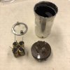
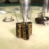
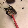
Just thought I'd post an update. I've finished replacing the Ceracaps and started working on the can caps. The one below is the 4x100uF/100v with the common positive for the bias supply circuit. I'll be putting it back together tomorrow.
IMG_1031.jpegIMG_1032.jpegIMG_1033.jpegIMG_1039.jpeg
IMG_1036.jpegIMG_1039.jpeg
 
Yes, that is exactly the way that I do it. I'm fortunate to have a box of NOS "FP" style can capacitors. I use them to extract the metal mounting ring. That is the most difficult part to remove without damage on the original amplifier. Whilst placing capacitors below deck is an option with much equipment, the Scott doesn't afford much room below. That's the reason I use this exact method as well. It takes me about an hour to rebuild a capacitor, depending on how hard it is to extract the "guts" from the old one.
 
This is a great thread--and that LK-72 is beautiful. I have an LK-72 that I've spent quite of bit of time restoring. I have a couple questions. Does anyone have a faceplate like mine (or the all gold or all silver version)--even if it is rough? If you'd be willing to sell, that would be great. If not, would someone be able to make a full size copy of it? I am working on getting a replica made and I need a full-size exact image in order to make it the correct size, getting the holes properly spaced, and do the correct lettering. As an aside--IF I am able to do this, this process might be helpful to others that want the same sort of thing. 2) Someone mentioned knobs on eBay--does anyone know the seller? I'm going through this as I am moving overseas and very concerned about damage to the unit, no matter how well packed, so trying to do some things in case I need to do a repair as a backup. Also, another question--does anyone have any experience running these Scott tube amps on a 220V to 110V step down transformer, especially as the frequency in Ireland is different?

 

Attachments

  • My Scott LK72.jpg
    My Scott LK72.jpg
    98.6 KB · Views: 4
Back
Top Bottom