• The move to the new server is done. There are some software and database maintenance updates in process. This has us passing the hat around to help out. We appreciate any donations. Seriously, even a dollar helps. The payment page may be found here - https://www.audiokarma.org/support.html

My first tube amp - Scott LK-72-B

I have a po
That's a great thread. I'll definitely give some thought to restuffing and will see how the cost compares to buying the Hayseed-Hamfests. Any suggestions what brand or type of capacitor to use for this application and how to make sure I order caps that will all fit inside in the can?

Thanks again.
I have my favorites but I also do not wish to step on any land mines this morning.
The ones I personally like are brand new, ordered from trusted wholesalers, and which compete for good value with other major brands.
That is to say, don't spend stupid money on capacitors.
In your shoes, given the extremely mint condition of your unit, I think I'd pay up for the hayseed caps because the sight of them onboard indicates that no corners were cut and that cost was no object on restoring this to perfect operating condition.
 
In your shoes, given the extremely mint condition of your unit, I think I'd pay up for the hayseed caps because the sight of them onboard indicates that no corners were cut and that cost was no object on restoring this to perfect operating condition.
Thanks. I was already leaning that direction, so will probably go that route.
 
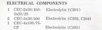
I would buy two F&T 32/32 cap cans ($11.25 US each at tubesandmore.com); replicate the 4x100 Common Positive can by putting four 100uf/100v radial caps (tiny) on a tag strip or little piece of perf board; find an empty space to put two 22uf/450v ; and mount the two 25uf/25v (tiny) directly on what they connect to. The whole deal would cost less than one of those Hayseed or CE cans. And I wouldn’t spend money for Sprague caps; they’re just selling a name. Two modern Nichicon or whatever 3.9 or 4.7 uf to replace the 4 uf ones should cost next to nothing.IMG_0011.jpeg
 
Last edited:
I'd go with the yellow Mallorys or some orange drops, because you can get real ones cheap enough from Mouser or your favorite electronics parts wholesaler...
I was looking for the yellow Mallorys, but was having a hard time finding them and that brand didn't come up on Mouser or Digikey. Then I read somewhere that they are made by CDE Cornell Dubilier now. Is this 150 series the same cap you were suggesting? https://www.mouser.ca/ProductDetail/539-150104J400EC

During my searches I also came across a post recommending the Cornell Dubilier WMF series polyester film-and-foil capacitors for coupling caps. Any thoughts on those? They are about the same price as the 150 series. https://www.mouser.ca/ProductDetail/598-WMF4P1K-F

I find it very difficult to choose capacitors, and tend to suffer from analysis paralysis when there so many options and differing opinions. So I appreciate all the advice.
 
I was looking for the yellow Mallorys, but was having a hard time finding them and that brand didn't come up on Mouser or Digikey. Then I read somewhere that they are made by CDE Cornell Dubilier now. Is this 150 series the same cap you were suggesting? https://www.mouser.ca/ProductDetail/539-150104J400EC

During my searches I also came across a post recommending the Cornell Dubilier WMF series polyester film-and-foil capacitors for coupling caps. Any thoughts on those? They are about the same price as the 150 series. https://www.mouser.ca/ProductDetail/598-WMF4P1K-F

I find it very difficult to choose capacitors, and tend to suffer from analysis paralysis when there so many options and differing opinions. So I appreciate all the advice.
Either of those should work just fine.
Mallory no longer makes the Mallory 150 but cde still prints an M logo on them for those of us that dispise change.

Analysis paralysis is real.
It helped me to realize that the folks with opinions have not done any double blind testing. Their opinion is based on usually replacing an old failed component with a new one that works.
The difference in sound isn't due to a difference in dielectric it has more to do with the fact that the power tubes both work correctly and hold bias...

Don't put a whole lot of thought into it.
It's like buying flat washers at the hardware store.
If one store has them 2c cheaper, you buy them there, because a flat washer is a flat washer.
Capacitors are about the same.
If the specs match what you need, then give it a try.
 
Last edited:
A question was asked about 630 VDC capacitors as opposed to 400 VDC. I would guess that 95% of the capacitors that I have in my storage boxes are 630 VDC ones. Why? Because they will work with all voltages 630 Volts and below. I don't want to stock a bunch of them when "One Voltage Fits All", usually. Also, the lower voltage capacitors usually don't cost substantially less or less at all. And, they are often not any smaller than the 630 VDC capacitors. Hope this helps.
 
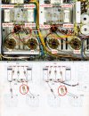
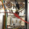
The capacitors marked with red arrows in the photo are what you will be testing.
One side should have positive DC on it, generally the side closest to the driver tube.
The end that connects to the (big) power tube should have a negative voltage on it of something like 12 to 20 volts.
If it has positive voltage on the power tube side then the cap has failed.

Test using the red probe of your dvom on dc volts setting with the black lead connected to chassis, or ground.

The advice to change them out as cheap insurance is great advice.
I'd go with the yellow Mallorys or some orange drops, because you can get real ones cheap enough from Mouser or your favorite electronics parts wholesaler...

Have fun, that Scott is a real Gem, there's not a lot left in that good of condition.

Happy New Year everyone! I got busy with other projects and had to put the Scott aside for awhile, but I'm starting to get back at it again. I finally checked the coupling caps for DC leakage. I measured negative voltage ranging from about -24V to -29V on the side of the caps closest to the 7591 tubes. The other side was positive and on V4 and V104 it was about 215V and on V5 and V105 it was about 83V as marked in attached image. Does that sound right or is there something wrong here? I will be replacing these caps, but just wondering what the proper voltage should be.

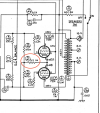
I was also checking resistors and noticed something that doesn't match the schematic or original assembly manual. As you can see in the image below there are four 2 ohm resistors (red, black, gold, gold), but the assembly manual only describes two 3.3 ohm resistors in this position, one for each channel. I suppose two 2ohm accomplish the same thing as one 3.3ohm, but just wondering if this is ok or was perhaps done for another reason? I was looking at this area because I was trying to understand how to adjust bias and saw some people referencing the 3.3ohm resistors as a measurement point as shown in attached clip of schematic.

I'm finally putting an order together at Mouser and will be going with 150 series capacitors. If there is anything else I should be ordering or any mods or updates to consider, please let me know.

Thanks very much.

scott-resistors-unknown.jpgScreen Shot 2025-01-01 at 5.42.02 PM.png
 
Last edited:
I would replace the cathode resistors with 1Ω 1%. The test points will then measure as 1mV = 1mA.

Jack
 
Last edited:
I wold replace the cathode resistors with 1Ω 1%. The test points will then measure as 1mV = 1mA.

Jack

Thanks for the quick reply. I'm still not completely clear on the bias procedure or where the test points are. The most detailed description I could find was in this post at diyaudio. The author says to adjust the bias voltage pot to .23/.24 volts for each channel... which will give a 70ma current value for each pair of output tubes, and with the DC balance adjusted to 0 Volts, you'll have 35ma per tube which is what Scott specified." He the end of the post he also says "The entire process can be done from the top of the chassis if you install individual 10ohm plate sensing resistors and test point jacks in place of the 3.3ohm resistors."

Do you know why he would suggest 10ohm rather than 1ohm like you recommend? Sounds like the actual resistor value doesn't matter that much, but using a 1ohm will simplify the math to convert the mV to mA? Am I understanding correctly? Would I replace the four 2ohm resistors that are there now with four 1ohms? Is 1 watt ok?

Thanks again.
 
"The entire process can be done from the top of the chassis if you install individual 10ohm plate sensing resistors and test point jacks in place of the 3.3ohm resistors."
Not to nitpick, but these aren't plate sensing resistors. Cathode current in a 6L6 amplifier includes both the plate and screen.
Sounds like the actual resistor value doesn't matter that much, but using a 1ohm will simplify the math to convert the mV to mA?
Yes, it's mostly about the math. 10Ω and 3.3Ω resistors were common back when the typical meter was a 20K/volt VOM. With everything now being digital, it's no problem to read the voltage accurately across a 1Ω resistor. All my amps use this value. About the power rating, 1W is overkill, but most of the 1/2W versions now are very small and have very thin leads, more like the old 1/8W resistors from 20 years ago. The 1W size will work much better from the standpoint of installation.

Kyoto El34 Bias.JPG

Jack
 
Thanks Jack. That's very helpful. I've added four 1ohm 1% 1W resistors to my order. Would you be able to describe the process to adjust bias with these 1ohm resistors in place? I'm not worried about working from the top of the chassis.

Thanks again,

Andy
 
Would you be able to describe the process to adjust bias with these 1ohm resistors in place?
The LK-72B schematic indicates about +460V on the output tube anodes. I would adjust the two bias pots and the DC balance pots for about 30mA at each cathode. That's a total dissipation (plate plus screen) of about 14W at each tube. The original bias test points and the procedure in the manual will no longer be valid, so you'll need to measure the voltage at each cathode.

Jack
 
Hi everyone,

Thought I'd share some pics of a Scott LK-72-B I picked up recently. It's in very nice condition and looks original to me. I've been listening to it for a few weeks and it sounds really nice too. Only thing I've done is get the tubes tested. They all tested good except one 6U8, which oddly showed a short on one tester, but not on another. So to be safe I replaced them both with a pair of vintage RCAs.

I know I should consider replacing many other parts, and I have been doing a lot of reading on these forums and about what should be done, but if anyone has any suggestions on where to start I would really appreciate it.

One question I do have is about the bridge rectifier. I've read it should be replaced with a silicone rectifier, but I would really appreciate a recommendation for a specific product. Most of the discussions I've found about this are older and reference items that don't seem to be available any more.

Thanks and here's a few photos.

View attachment 3328872View attachment 3328881View attachment 3328880View attachment 3328879View attachment 3328878View attachment 3328877View attachment 3328876View attachment 3328875View attachment 3328874View attachment 3328873

Looks like it was in a time capsule, very nice.
 
The LK-72B schematic indicates about +460V on the output tube anodes. I would adjust the two bias pots and the DC balance pots for about 30mA at each cathode. That's a total dissipation (plate plus screen) of about 14W at each tube. The original bias test points and the procedure in the manual will no longer be valid, so you'll need to measure the voltage at each cathode.
Forgive my ignorance, but I'm pretty new to this stuff and sometimes need things spelled out for me. How do I "measure the voltage at each cathode"? The diyaudio post I linked to above says to "measure the voltage drop across the 3.3 ohm resistor for each channel's cathode ground wire." Does that mean I place my multimeter leads on either side of the resistor as pictured below?

Thanks.

IMG_0786.JPG
 
Does that mean I place my multimeter leads on either side of the resistor as pictured below?
Yes, you would measure the voltage across each 1Ω resistor. Being as they all go to ground, you could also just measure from ground to each cathode, one at a time.

Jack
 
Yes, you would measure the voltage across each 1Ω resistor. Being as they all go to ground, you could also just measure from ground to each cathode, one at a time.

Jack
Thanks again Jack. Does adding four 1Ω resistors provide the ability to individually bias each tube even though there is still only one bias pot for two tubes? I've been doing a lot of reading here this this weekend and came across a bunch of threads discussing IBAM (Individual Bias Adjustment Mod). Most of the threads I found seem to apply to Fisher amps, so not sure if that's something I should consider for my Scott.

Also came across this post where Jim McShane says "Keep in mind you also need to modify the grid resistor value to use the modern 7591As. There have been some cases where the new production 7591A tubes have had trouble in circuits using a very high value grid resistor - as vintage Scotts, Fishers, and others sometimes do. The best solution is changing all the grid resistors to 200K-220K from the original 330K value, since often the factory spec resistors exceeded the maximum recommendations. For instance, Fisher routinely used those 330K carbon resistors that would often drift up to 360K over time! "

Is that something I should consider doing? I checked the 330K resistors in-circuit and they tested around 200-240K. I know that's not a reliable way to measure them, but I was planning to order replacements in case they do test out of spec when I start replacing components.

I've been looking for a quad of 7591 tubes for my Scott, but most vintage or NOS I've seen are pretty expensive, like $600 to $800CAD or more on eBay right now. If matched quads are hard to find or out of my budget, I just want to make sure I can bias everything properly and have the ability to use new tubes as well.

Thanks again. Really appreciate all of your assistance.

Andy
 
Andy, the 1Ω resistors only allow you to measure the bias current at each tube. The LK-72-B allows you to adjust each tube's idle current individually by using the Bias and DC Balance pots. this method isn't quite as straightforward to adjust as individual bias pots, but the result is the same.

I would definitely follow Jim's advice on the resistor change. Even if they're still exactly 330K, that's too high. Four 220K resistors are cheap insurance against thermal runaway in these tubes.

I have no experience with reissue 7591 tubes, other than Jim McShane's warnings about multiple failures with JJ. That was a few years ago though, so maybe the company has improved. Their other tubes seem to be fine. Antique Electronic Supply sells a matched quad of Tung-Sol reissues for about $200 US, and that's the way I'd go. Prices for NOS are much higher now than I would ever consider reasonable, and I would also question whether there really are enough good ones left to accomplish a matched set.

Hope this is helpful!

Jack
 
What a beautiful circuit. Question to those who may know, why is it ok for the two transformers in the build to be aligned in the same direction? Wouldn't that create overlapping magnetic fields, inductance, noise?
 
Back
Top Bottom