• The move to the new server is done. There are some software and database maintenance updates in process. This has us passing the hat around to help out. We appreciate any donations. Seriously, even a dollar helps. The payment page may be found here - https://www.audiokarma.org/support.html

Need help getting rid of hum

The doubler is a pair of diodes and caps wired in a particular way off the HV winding of the transformer. Not sure if yours are on the board are elsewhere, but on the board would be a logical place for the diodes to live. The resistors are unrelated to that.


Do you happen to have a scope?
 
gadg - I have a scope (Rigol DS1054z with the upgrade: https://www.tequipment.net/Rigol/DS1054Z/Digital-Oscilloscopes/), a Fluke 115 multimeter with a capacitor and frequency features (https://www.fluke.com/en-us/product/electrical-testing/digital-multimeters/fluke-115), a signal generator whose max is 60MHz (http://www.koolertron.com/koolertro...-generator-frequency-meter-266msas-p-836.html) and an FM alignment generator (https://www.valuetronics.com/product/1000a-sound-technology-generator-used).

The doubler is indeed on the SDS board. I read that somewhere in my research.
 
Have you checked all the resistors on the SDS board as well the diodes? I am amazed how resistors can look brand new yet test off value.
 
Both diodes measure 0.423 vdc. They are 3A diodes. R2 and R3 measure 465 ohms which is right on. R1 measures 0.2 ohms but is supposed to be 15. I don't want to cut anything so don't know how to account for the bad measurement. Probably connected to other components. I can't get to the other resistors R4 to R8 - my probes won't reach between the caps and I can't get to the back of the board without cutting wires.
 
What do I need to put my multimeter on to test R1.... If mine is 0.2 OHMS that should help. I don't mind making measurements like this with things off it is with it ON that my PSTD kicks in from when I caused a little fire in 800c lol
 
Tony - You want to measure ohms when measuring resistors. Put a probe on each side of the resistor, doesn't matter which one.
 
I'll check soon as I need to put my bottom cover back on... Waiting for it to cool down as I had it on this AM
 
It's not even 1 ohm apparently so put your meter on something that low. Is there no AUTO setting on the meter where it just reads whatever?
 
Just clipped my death cap. It measured 125nF which is 0.13uF. It's supposed to be 0.01uF. I'm replacing it with 0.01uF 300vac. It was 600v. Hope 300 is enough.
 
Last edited:
Somethoughts:

1.SInce its 120hz doesn't that mean its really 60hz but the voltage doubler makes it 120hz. Would that mean the problem is before the voltage doubler circuit?The new caps you ordered will help with that.
2.I don't think its the grid resisitors as it would happen no matter what the input selection is but anything is possible.
3.Maybe turn it on with speakers hooked up with it upside and poke things with a plastic tooth brush to see if this does anything.

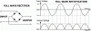
The 120Hz doesn't come because of the doubling of the voltage. The 120Hz is an artifact of the rectification which essentially flips the bottom half of the sin-wave up so that for each full swing of the sign wave you have two pulses of DC. Now could the voltage doubler caps be going bad and transmitting those double humps (at a rate of 120Hz)? Absolutely, but it could be a lot of other things too.

Top of pic is 60HZ (pure sin wave). Bottom of pic is 120Hz (pulsing DC).

XS66u.gif
 
Thanks for the education, Tim. If it were half-wave rectification, I believe the output graph would have spaces between the tops where the bottoms were rectified out.

To be honest, I'm at the point where I'm not sure if I'm getting 60 or 120 because it sounds like 120 with the unit just sitting there, but when I move my hand near the input wires, I get a strong 60.

Anyway, I'm about to replace the death cap. I'm going to look for a probe that's long enough to reach between the SDS board caps and measure the resistors. I feel like Aaron Rodgers in the Dec 2015 last few minutes. Hopefully I will feel like Richard Rodgers after testing the new cap. :)
 
Thorne,

There are audio files on the internet that will let you listen to the difference between 60Hz hum and 120Hz hum. Of course if your noise is dirty the distinction could be difficult to hear.

A possibility is that the caps in the power supply are failing and not smoothing that pulsing DC waveform. I don't know if you can measure the caps in circuit (with all voltage bled off of course) to see what is the capacitance and ESR and DCR (any leakage which is bad) for them. I haven't checked but I have a strong belief that the phono tubes use rectified and smoothed DC in the same manner. If the smoothing for the DC heater circuit is not happening that could introduce 120Hz hum. I'm just not sure how much and if that might be part of your problem as AC heaters (or dirty heater supply) probably wouldn't be that intrusive (would they?). More likely you have B+ filtering problem or some other problem such as a part failing or some ground issues or a wire running close to something that it shouldn't - thus picking up the hum.
 
I have those 3 frequency files downloaded (180Hz too). As a guitar player for 58 years, I can hum to you A 220 and be within a 1/2 step if not within tens of cents. The open A string is 110 so 120 would be just north of A# but not quite B. 60Hz would be on a bass guitar. The issue is that I'm hearing 60Hz with 120Hz overtones.

I believe that since the tops of the caps are live with the unit powered on, I can measure the voltage. Whether series and parallel rules apply when measuring live, I don't know. I do have an ESR meter but don't know if it can be used with out clipping one side of a cap.

New death cap is in. Going to clean up the area, button up and listen for hum. Thanks for the responses, Everyone.
 
I have those 3 frequency files downloaded (180Hz too). As a guitar player for 58 years, I can hum to you A 220 and be within a 1/2 step if not within tens of cents. The open A string is 110 so 120 would be just north of A# but not quite B. 60Hz would be on a bass guitar. The issue is that I'm hearing 60Hz with 120Hz overtones.

I believe that since the tops of the caps are live with the unit powered on, I can measure the voltage. Whether series and parallel rules apply when measuring live, I don't know. I do have an ESR meter but don't know if it can be used with out clipping one side of a cap.

New death cap is in. Going to clean up the area, button up and listen for hum. Thanks for the responses, Everyone.

Yes, measuring components in-circuit is always a crap-shoot as to whether there are parallel paths around the component. I'd give it a try and then if you don't get an expected reading you could dig deeper. It should measure within tolerance of the capacitance if there isn't a parallel path(s) around the cap.
 
What does it mean when a resistor value keeps decreasing? There are 3 (R6-R8) on the SDS board that do that. They are connected to e-caps and each other. Their values should read 82k and two 330's. The MM starts at like 2M and keeps decreasing until I have no patience to hold the probe anymore. R1 is supposed to be 15 but measures 0.2 - it is connected to other parts so I don't know if it needs replacing. It's soldered to the SDS board unfortunately. It doesn't look damaged. It looks brand new. R2-R5 are fine, only slightly off except R5 which is 20k and should be 22k.

EDIT: I'm checking the value of all resistors in the preamp and PHONO areas. Question... When resistors are connected in series, that doesn't affect their value, right? It's only when they're in parallel that you have to do math, right? I've got some resistors not connected in parallel that are off e.g. spec at 470k but measure 417k. That's almost 13% off. Do we allow more than 10% difference? Or does it depend on what area e.g. some areas require a tighter tolerance?

For example, the attached image, the resistor pointed to... It's BRN-BLK-YEL which is 100k. It measures 58k. I believe it needs to be replaced. Yes? The resistor to its left (BRN-BLK-BLK) is attached to it in series.

 

Attachments

  • 0527201553.jpg
    0527201553.jpg
    145.5 KB · Views: 3
Last edited:
I have a list of 8 resistors that are significantly off their rated value. I'll need my question above answered before I can say they must be replaced.
 
What does it mean when a resistor value keeps decreasing? There are 3 (R6-R8) on the SDS board that do that. They are connected to e-caps and each other. Their values should read 82k and two 330's. The MM starts at like 2M and keeps decreasing until I have no patience to hold the probe anymore. R1 is supposed to be 15 but measures 0.2 - it is connected to other parts so I don't know if it needs replacing. It's soldered to the SDS board unfortunately. It doesn't look damaged. It looks brand new. R2-R5 are fine, only slightly off except R5 which is 20k and should be 22k.

EDIT: I'm checking the value of all resistors in the preamp and PHONO areas. Question... When resistors are connected in series, that doesn't affect their value, right? It's only when they're in parallel that you have to do math, right? I've got some resistors not connected in parallel that are off e.g. spec at 470k but measure 417k. That's almost 13% off. Do we allow more than 10% difference? Or does it depend on what area e.g. some areas require a tighter tolerance?

For example, the attached image, the resistor pointed to... It's BRN-BLK-YEL which is 100k. It measures 58k. I believe it needs to be replaced. Yes? The resistor to its left (BRN-BLK-BLK) is attached to it in series.

Well, the fact that the resistors values are moving around might mean that there is a parallel path with at least one cap in it that is charging from the small voltage from your MM. You might have to lift one end of the resistor to get a good measurement on it.

You are right - when they are in series you can just measure the one, but if both series resistors are in a bigger circuit there might be other components paralleled or networked around the resistors that would affect the measurement. Again to get a good measurement you might have to lift one end of it. Sorry.
 
so the reason I was asking about a scope, if you can probe the DC output of the various power supply nodes, especially the one for the phono tubes, that would tell you if the problem is with the power supply or not. If you get no ripple worth talking about on the feed to the phono tubes, the power supply ain't what ails it. Might need a blocking cap of some reasonable value between the scope probe and the DC source just to make sure you don't exceed the probe's voltage ratings. Value not important, 0.01 - 1.0 film cap, whatever is handy. Since it doesn't hum on anything but the phono, I think we can focus just on the phono supply. I suspect you're going to see a pretty flat line since the phono stage should come basically at the tail end of the filter chain.

and @TimD is right about it being just an artifact of full wave rectification. Its double mains frequency, 120 in the US, 100 elsewhere. Fishers happen to use a full wave doubler but you'd get exactly the same ripple frequency from a full wave bridge (see your bias supply) or a full wave center tap (tube rectifier) setup.
 
gadg - It also hums on TAPE HEAD. But TAPE HEAD is connected to PHONO, just uses a different EQ. I will try your suggestion probing for DC. Thanks.

And since I have some of the same resistors that measure off their value and they measure the same amount off their value, I will assume it is because they are in series but are also part of a bigger circuit that has parallel connections. That makes sense. It's difficult for me to eyeball the larger circuit because I'm not sure where to draw the circuit boundaries.

But first !... Let's see what the new death cap does. Watch this space ! (oh man, 200 posts. Sorry gang)
 
Last edited:
Back
Top Bottom