

You are using an out of date browser. It may not display this or other websites correctly.
You should upgrade or use an alternative browser.
You should upgrade or use an alternative browser.
Need help getting rid of hum
- Thread starter thornev
- Start date


Tim D
Super Member
Well, that was interesting trivia, but it appears to be as-designed.
You said that the Aux has no hum, right? If so, then the focus might be on the phono/tape preamp area. It's not that complicated. So what voltages do you get on the plates for V16 and V17 on pins 1 and 6? The schematic says 105V on pin 1 and 85V on pin 6. Are you close? A big difference in voltage from the schematic might lead us to believe the flow though part of these tubes isn't right.
You said that the Aux has no hum, right? If so, then the focus might be on the phono/tape preamp area. It's not that complicated. So what voltages do you get on the plates for V16 and V17 on pins 1 and 6? The schematic says 105V on pin 1 and 85V on pin 6. Are you close? A big difference in voltage from the schematic might lead us to believe the flow though part of these tubes isn't right.

thornev
Super Member
I just sprayed DeOxit D5 on the on/off switch to eliminate a dirty pot as the problem. I have DeOxit FaderF5 too.
Correct, no hum on AUX. That was fixed by Dave's "reconnect the 2 ends of the blue wire off the t-strip" procedure in some other "hum thread."
Voltages (with no signal at the input jacks):
V16 pin 1 = 110 vdc
V16 pin 6 = 90
V17 pin 1 = 114
V17 pin 6 = 90
All my voltages are on the high side but not high enough to cause concern. I've tested just about everything in the chassis that can be tested for voltage. Nothing seems out of spec. Some of the voltages coming off the SDS board are higher than should be. I can document them, what they should be, and where those wires go (although I think that's already documented on an earlier page. yes, here:
https://www.audiokarma.org/forums/i...etting-rid-of-hum.914717/page-4#post-13813744 Note that SDS values for A and C are reversed.
Updated values here:
https://www.audiokarma.org/forums/i...etting-rid-of-hum.914717/page-5#post-13816259
and here:
https://www.audiokarma.org/forums/i...etting-rid-of-hum.914717/page-6#post-13822724).
Correct, no hum on AUX. That was fixed by Dave's "reconnect the 2 ends of the blue wire off the t-strip" procedure in some other "hum thread."
Voltages (with no signal at the input jacks):
V16 pin 1 = 110 vdc
V16 pin 6 = 90
V17 pin 1 = 114
V17 pin 6 = 90
All my voltages are on the high side but not high enough to cause concern. I've tested just about everything in the chassis that can be tested for voltage. Nothing seems out of spec. Some of the voltages coming off the SDS board are higher than should be. I can document them, what they should be, and where those wires go (although I think that's already documented on an earlier page. yes, here:
https://www.audiokarma.org/forums/i...etting-rid-of-hum.914717/page-4#post-13813744 Note that SDS values for A and C are reversed.
Updated values here:
https://www.audiokarma.org/forums/i...etting-rid-of-hum.914717/page-5#post-13816259
and here:
https://www.audiokarma.org/forums/i...etting-rid-of-hum.914717/page-6#post-13822724).
Last edited:
Tim D
Super Member
Those voltages look good actually. I was hoping for a smoking gun like they went low or something.
I was thinking the caps on the grids might be going bad - passing DC, but it looks like no from those voltages. It might be useful to check the caps around those tubes to be sure though. C13, C14, C16 and C17. Got a meter for that?
I was thinking the caps on the grids might be going bad - passing DC, but it looks like no from those voltages. It might be useful to check the caps around those tubes to be sure though. C13, C14, C16 and C17. Got a meter for that?
thornev
Super Member
vI have capacitance and frequency on my Fluke 115. Great meter. I also have an ESR meter.
Those 4 caps are the ones I just replaced a few weeks ago with Russian PIO. I read in more than one forum that PIO caps in these positions can improve significantly the audio. I wasn't able to do a good A/B test so I can't say. But when I crank the volume playing vinyl, this 500-C does justice. I cannot measure those caps without removing a leg on each. I'm avoiding having to remove solder and re-solder which risks damaging parts from heat, building solder globs in places where old solder just won't be removed and other lame excuses. I believe I did measure those PIO caps before I installed them as I usually do with new parts. Of course that doesn't account for damage that may have occurred since install.
I don't suppose there's a method to measure the caps with the unit powered on? Of course not - the capacitance goes up and down. Maybe voltage from a neighboring resistor?
A few pages back I mentioned 8 resistors whose values are over 15% off. But I didn't consider that they're part of a larger circuit that consists of components wired in parallel. Since the measured values are UNDER the rated values, their being part of a parallel circuit would explain that behavior. Also, where there are twin circuits for tubes that are part of left and right channels, and the twin circuits measure almost exactly the same UNDER value, I believe it's safe to say that those values are normal. It's too much of a coincidence otherwise that they both fail with the same values.
So where does this leave me? Same place I was weeks ago. Hamfest power stage cap cans are on order. I don't believe it's unreasonable to suspect the SDS board as the source of the problem. After all it does contain a lot of e-caps (13), 1 film cap, 1 diode bridge rectifier, 2 diodes and 8 resistors, an 8.2-ohm 5w sucker that's supposed to manage the voltage, parts that feed into the death cap, and all that is a critical part of getting a 500-C off to a quiet start. And that damn board did shock me big time - it doesn't like me.
gadget suggested scoping the problem, but for some unknown reason I've been unable to get the scope to work. It just doesn't see the signal I send thru the PHONO jacks.
I'm wondering about the tube sockets. I have retensioned some of them.
gadget also mentioned that my volume switch is missing the hat. Also he mentioned that I've got the 220k resistors on my IBAM board instead of by the output tubes, but since the IBAM wiring stays away from the power section, I didn't think it is a problem. Still, if it is suspect, that's not a trivial task.
Well, it's time for our daily neighborhood walk. Thanks again, Tim, for reaching out. I do appreciate it.
EDIT: There must be some way that I can prove that the hum emanates from the SDS board, some method of tracing each lead off the board and looking for some symptom. For example, if I use a scope to trace AC and (if I can get a wave) see that it contains the 60 and/or 120 hum.
Those 4 caps are the ones I just replaced a few weeks ago with Russian PIO. I read in more than one forum that PIO caps in these positions can improve significantly the audio. I wasn't able to do a good A/B test so I can't say. But when I crank the volume playing vinyl, this 500-C does justice. I cannot measure those caps without removing a leg on each. I'm avoiding having to remove solder and re-solder which risks damaging parts from heat, building solder globs in places where old solder just won't be removed and other lame excuses.
I believe I did measure those PIO caps before I installed them as I usually do with new parts. Of course that doesn't account for damage that may have occurred since install.I don't suppose there's a method to measure the caps with the unit powered on? Of course not - the capacitance goes up and down. Maybe voltage from a neighboring resistor?
A few pages back I mentioned 8 resistors whose values are over 15% off. But I didn't consider that they're part of a larger circuit that consists of components wired in parallel. Since the measured values are UNDER the rated values, their being part of a parallel circuit would explain that behavior. Also, where there are twin circuits for tubes that are part of left and right channels, and the twin circuits measure almost exactly the same UNDER value, I believe it's safe to say that those values are normal. It's too much of a coincidence otherwise that they both fail with the same values.
So where does this leave me? Same place I was weeks ago. Hamfest power stage cap cans are on order. I don't believe it's unreasonable to suspect the SDS board as the source of the problem. After all it does contain a lot of e-caps (13), 1 film cap, 1 diode bridge rectifier, 2 diodes and 8 resistors, an 8.2-ohm 5w sucker that's supposed to manage the voltage, parts that feed into the death cap, and all that is a critical part of getting a 500-C off to a quiet start. And that damn board did shock me big time - it doesn't like me.
gadget suggested scoping the problem, but for some unknown reason I've been unable to get the scope to work. It just doesn't see the signal I send thru the PHONO jacks.
I'm wondering about the tube sockets. I have retensioned some of them.
gadget also mentioned that my volume switch is missing the hat. Also he mentioned that I've got the 220k resistors on my IBAM board instead of by the output tubes, but since the IBAM wiring stays away from the power section, I didn't think it is a problem. Still, if it is suspect, that's not a trivial task.
Well, it's time for our daily neighborhood walk. Thanks again, Tim, for reaching out. I do appreciate it.
EDIT: There must be some way that I can prove that the hum emanates from the SDS board, some method of tracing each lead off the board and looking for some symptom. For example, if I use a scope to trace AC and (if I can get a wave) see that it contains the 60 and/or 120 hum.
Last edited:
Tim D
Super Member
Thorne,
I don't know an easy way to measure capacitance while it's got power on it. I only know how to use the meter when power is not applied and the cap is discharged.
In terms of measuring resistors in-circuit - if you get a higher than spec measurement then the resistor is actually over its rated resistance. If you get a value lower than spec then it could be either out of spec or there is a parallel path around the resistor. I did this on my KX-100 and found that I could measure a majority of resistors in-circuit. Sometimes inspection of the diagram will show that there are no other paths around the resistor.
Can you get the scope to do anything? Is it broken?
I don't know an easy way to measure capacitance while it's got power on it. I only know how to use the meter when power is not applied and the cap is discharged.
In terms of measuring resistors in-circuit - if you get a higher than spec measurement then the resistor is actually over its rated resistance. If you get a value lower than spec then it could be either out of spec or there is a parallel path around the resistor. I did this on my KX-100 and found that I could measure a majority of resistors in-circuit. Sometimes inspection of the diagram will show that there are no other paths around the resistor.
Can you get the scope to do anything? Is it broken?
thornev
Super Member
If I crank up the signal voltage to 950mV, I can get a nice AC wave with more amplitude. Just gotta watch that speaker selector.
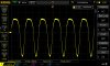
V16 and V17... I'm getting real nice sine waves now. Just had to play around a little more. The tops are nice and round, but the bottoms are pointy. And the bottoms go farther below zero than the tops go above zero. How do I interpret that? Pin 6 waves look nice. Pin 1 waves have pointy bottoms. Kind of looks like a rectified wave.
V14 and V15 pins 1 and 6 - ugly-looking waves. V14 tops are squared with a slope upward. Bottoms on V14 are rounded but thick. Bottoms on V15 are square with a slope downward. V15 tops are nicely square and level. Interpretation?
See attached images. Tube and pin number are file names. Setup was 950mV with a 1kHz signal, no offset, 50% duty (50% is default - I didn't know what DUTY is).
V16 and V17... I'm getting real nice sine waves now. Just had to play around a little more. The tops are nice and round, but the bottoms are pointy. And the bottoms go farther below zero than the tops go above zero. How do I interpret that? Pin 6 waves look nice. Pin 1 waves have pointy bottoms. Kind of looks like a rectified wave.
V14 and V15 pins 1 and 6 - ugly-looking waves. V14 tops are squared with a slope upward. Bottoms on V14 are rounded but thick. Bottoms on V15 are square with a slope downward. V15 tops are nicely square and level. Interpretation?
See attached images. Tube and pin number are file names. Setup was 950mV with a 1kHz signal, no offset, 50% duty (50% is default - I didn't know what DUTY is).
Attachments
Last edited:
Tim D
Super Member
Thorne,
Yes, the V16 and V17 pin 1 look like the 120Hz signal from a full wave rectified AC input. See my post #191 pic. Do you get that same signal both with and without your signal injection? I.e. Is that coming from the power supply on the B+? The clipped signals on some of the others might be because your input is just too strong and it is overdriving the preamp.
Yes, the V16 and V17 pin 1 look like the 120Hz signal from a full wave rectified AC input. See my post #191 pic. Do you get that same signal both with and without your signal injection? I.e. Is that coming from the power supply on the B+? The clipped signals on some of the others might be because your input is just too strong and it is overdriving the preamp.

The grounds I was thinking of were the connection from the outer ring of the RCA jack to wherever it goes. No idea if its meant to go straight to chassis, or ground through a shield to someplace. Never worked on one, so I'm not familiar with the specific construction. I was just thinking that it would be worth verifying that whatever is there is as it ought to be. Looks to me like there is a 10 ohm between the outer ring and ground. R13 and "1/2 R17", whatever that means. Basically if you're reading 0 ohms the 10 ohm resistor has been bypassed somehow, if its open then its missing. If you get ~10 ohms its probably as it ought to be. Problems with the grounds can introduce 60hz hum. Won't make 120hz though, just thinking since you apparently have both it might be a source of part of it.
I was thinking of checking for power supply ripple on the power supply side of the resistors on pins 1 and 6. That would show you just what is coming out of the supply. No signal injected into the phono inputs, volume doesn't matter but I'd keep it low just in case connecting things makes a pop. All 4 of those resistors go to the same point, so one check would tell us if the 120hz is coming out of the power supply or not. Looks like Fisher calls this "A" on the supply. That should be super clean, its the very last stage of the power supply and has gone through a bunch of filtering. If however that connection was made to the wrong point you'd get less filtering and it might explain this. A quick sanity check of the voltage at that node might tell us something too. Schematic calls for 215v. If its considerably higher you may be tapped into the wrong point on the board.
I was thinking of checking for power supply ripple on the power supply side of the resistors on pins 1 and 6. That would show you just what is coming out of the supply. No signal injected into the phono inputs, volume doesn't matter but I'd keep it low just in case connecting things makes a pop. All 4 of those resistors go to the same point, so one check would tell us if the 120hz is coming out of the power supply or not. Looks like Fisher calls this "A" on the supply. That should be super clean, its the very last stage of the power supply and has gone through a bunch of filtering. If however that connection was made to the wrong point you'd get less filtering and it might explain this. A quick sanity check of the voltage at that node might tell us something too. Schematic calls for 215v. If its considerably higher you may be tapped into the wrong point on the board.
thornev
Super Member
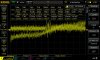
gadg - "All 4 resistors go to the same point" - I can't get to "A" on the SDS board. But from that board terminal is a PUR lead that goes to where R19/22 meet. The Fisher schematic's "A" is "E" on the SDS board, the 215v lead to where R19 and R22 meet on a 1-terminal t-strip. Those 2 resistors then connect to V17 pins 1 and 6. From that terminal is a PUR lead that connects to V16's R18 and R24, the equivalent resistors to V17's R19 and R22 and also another point where "A" connects to the other channel. I scoped with no signal at any input jacks, the selector switch on PHONO STEREO and the volume at more than half of maximum.
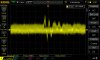
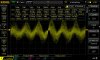
Images are attached for V17 "A" locations (didn't do V16 because images are same) trying different measurements on the scope as indicated in the image file names. All measurements are of AC. When I measured DC, the scope couldn't get a signal. That is inexplicable and I don't know why. Probably something on the scope I'm not doing correctly.
I'm confident that I've got the correct SDS board lead going to "A". I've done a lot of measuring. All the voltages in my chassis are on the high side. Larry saw that but didn't sound any alarms.
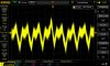
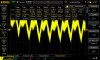
What's weird about the pin 6 scope measurements is that the wave completely changed shape from when I first scoped it to when I did it again later. I cannot explain the change, but I've attached both images. The changed waves have "diff wave" in the attached file's name. It may be because I changed the "trigger coupling" setting on the scope from DC to AC. There is also "channel coupling" that I figure is irrelevant since I'm measuring one channel. If I should redo the images with different settings, let me know.
I don't know how to interpret what the images display. I would expect however silence is represented, but apparently the images show the hum? However, the frequency is displayed in all the images, but it is not consistent. The frequency is all over the place.
Using a multimeter I measured the 2 "A" locations. I get 225 vdc at both V16 and V17 locations. Spec is 215. Both measurements were with volume at a little more than half way of max. The hum should have been plenty loud at that volume level.
EDIT: I forgot I measured all the SDS board terminals. I know you don't know what they are but you might be able to tell from the voltages and comparing them to the schematic.
SDS-A = 368 vdc (spec is 350, goes to phase controls)
SDS-B = 391 (Spec is 375, goes to wherever C91D goes)
SDS-C = 436 (spec is 430, this is B+ I believe, comes from C98)
SDS-D = 324 (spec is 295, goes to preamp circuits)
SDS-E = 224 (spec is 215, this is "A" on schematic)
SDS-F = 201 (spec is 160, this is "C" on schematic)
D and F are rather high. D is power to the MPX. F goes to R80 and then to the selector switch. Not sure the function of R80. Something to do with "C" on the schematic.
Images are attached for V17 "A" locations (didn't do V16 because images are same) trying different measurements on the scope as indicated in the image file names. All measurements are of AC. When I measured DC, the scope couldn't get a signal. That is inexplicable and I don't know why. Probably something on the scope I'm not doing correctly.
I'm confident that I've got the correct SDS board lead going to "A". I've done a lot of measuring. All the voltages in my chassis are on the high side. Larry saw that but didn't sound any alarms.
What's weird about the pin 6 scope measurements is that the wave completely changed shape from when I first scoped it to when I did it again later. I cannot explain the change, but I've attached both images. The changed waves have "diff wave" in the attached file's name. It may be because I changed the "trigger coupling" setting on the scope from DC to AC. There is also "channel coupling" that I figure is irrelevant since I'm measuring one channel. If I should redo the images with different settings, let me know.
I don't know how to interpret what the images display. I would expect however silence is represented, but apparently the images show the hum? However, the frequency is displayed in all the images, but it is not consistent. The frequency is all over the place.
Using a multimeter I measured the 2 "A" locations. I get 225 vdc at both V16 and V17 locations. Spec is 215. Both measurements were with volume at a little more than half way of max. The hum should have been plenty loud at that volume level.
EDIT: I forgot I measured all the SDS board terminals. I know you don't know what they are but you might be able to tell from the voltages and comparing them to the schematic.
SDS-A = 368 vdc (spec is 350, goes to phase controls)
SDS-B = 391 (Spec is 375, goes to wherever C91D goes)
SDS-C = 436 (spec is 430, this is B+ I believe, comes from C98)
SDS-D = 324 (spec is 295, goes to preamp circuits)
SDS-E = 224 (spec is 215, this is "A" on schematic)
SDS-F = 201 (spec is 160, this is "C" on schematic)
D and F are rather high. D is power to the MPX. F goes to R80 and then to the selector switch. Not sure the function of R80. Something to do with "C" on the schematic.
Attachments
-
 V17 A no signal measure all.jpg120 KB · Views: 4
 -
V17 A mesaure all no signal.jpg95 KB · Views: 1
-
 V17 A no signal.jpg106.4 KB · Views: 4
 -
 V17 pin 1 mesaure all no signal.jpg109.4 KB · Views: 4
 -
 V17 pin 1no signal.jpg80 KB · Views: 4
 -
 V17 pin 6 no signal.jpg82.4 KB · Views: 4
 -
 V17 pin 6 measure all no signal.jpg120.2 KB · Views: 4
 -
 V17 pin 6 diff wave no signal.jpg87.4 KB · Views: 4
 -
V17 with AC coupling mesaure all.jpg108.2 KB · Views: 0
-
 V17 pin 6 diff wave measure all no signal.jpg112.3 KB · Views: 4
Last edited:
Doesn't have to be measured at "A" on the board, if you find the "other" end of the 330k resistor on pin 1, that'll be electrically the same point. The 220k resistor from pin 6 also should go to that point if the schematic doesn't lie and sane construction applies. That should be a flat line, or with a very tiny amount of 120 hz ripple on it. If you've got a DC blocking cap or if the scope is set to AC coupling it won't show any DC. The DC voltage isn't what we're really concerned about here anyway. Leave it on AC, set the period 5ms and that should give a 120 ripple not quite 2 divisions wide if its going to be there. Probably should need to set the v/div to a low number. If you just get a flat line, the power supply is plenty happy. If you want to see what it looks like in a dirtier spot, the feed going to the output transformers will have significant 120 ripple on it.
The random junk right at the tube pin looks like the broad band hiss that tubes and old resistors make. I wouldn't read too much into it honestly. Its not 60 or 120 hz, and honestly none of it even appears to be anywhere in the audio band.
Voltages sound reasonable, not off enough to suggest "A" is connected to some other point on the board, which would bypass a bunch of the filter stages. Voltage at C depends on what mode you're in. Depending on settings it should be either 200 or 160. Other than that one you're within 10% and that could easily be explained by higher line voltage.
The random junk right at the tube pin looks like the broad band hiss that tubes and old resistors make. I wouldn't read too much into it honestly. Its not 60 or 120 hz, and honestly none of it even appears to be anywhere in the audio band.
Voltages sound reasonable, not off enough to suggest "A" is connected to some other point on the board, which would bypass a bunch of the filter stages. Voltage at C depends on what mode you're in. Depending on settings it should be either 200 or 160. Other than that one you're within 10% and that could easily be explained by higher line voltage.
dunno, I don't understand digital scopes honestly. I have a very hard time with equipment that is smarter than I am. I'm more the "turn dials until it looks right" type. Think you'd need to be poking at the point on the power supply where the output transformers connect to really see the ripple anyway. That won't be why it hums, just will serve to show what 120 hz ripple looks like.
thornev
Super Member
Well, I got the hum down to a reasonably low volume that I can listen with headphones and, crazy as it may sound, the surface noise of the vinyl is louder than the hum. All I did was plug in the shorting plugs and jiggle the input jacks until the hum got as quiet as I could get it. It didn't disappear as it's supposed to with shorting plugs, but I could get the volume up to about 1 o'clock before the hum became intolerable. So for now, I'm saying it's good enough. I know it can be better because AUX is almost completely silent. I'm listening to the White Album with headphones and it sounds so good !
Thank you Tony, Tim, Larry, Dave, the 451 Dave, Cat, Gadg and everyone else who stuck with me. It kept me going. Hayseed is on its way. Debating to get rid of the SDS board for several reasons. Anyway, for now, I'm outta here. ("famous last words" probably as they say)
Thank you Tony, Tim, Larry, Dave, the 451 Dave, Cat, Gadg and everyone else who stuck with me. It kept me going. Hayseed is on its way. Debating to get rid of the SDS board for several reasons. Anyway, for now, I'm outta here. ("famous last words" probably as they say)

"He'll be Back!" AK is like free penny candy to a kid with a sweet tooth and a distinct DISLIKE for Dentisststststststsstststststsssssss!
thornev
Super Member
By the way, I fixed the headphone/speaker channel-reversed problem. Didn't have to reverse the resistors. There are 2 wires that connect to the resistors in the cover behind the speaker selector switch. Remove the cover carefully by squeezing the 2 bottom clips, pulling up on the cover and the top clip pulls out easily. Just reverse the 2 wires that emanate from the headphone jack. Voila...done !