• The move to the new server is done. There are some software and database maintenance updates in process. This has us passing the hat around to help out. We appreciate any donations. Seriously, even a dollar helps. The payment page may be found here - https://www.audiokarma.org/support.html

Need help getting rid of hum

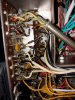
I disconnected the SDS board. One of the power transformer wires (which were stranded, not solid) to the SDS board was hanging on by a single strand ! Also, the YEL/BLK wire that goes to V14 contains 2 leads - the filament which connected to V14 pin 4 and what initially was thought to be a shield but later turned out to be a ground wire for the '+' lead of one of the board's e-caps. I'm hypothesizing that the transformer "single strand", the lack of shielding around the V14 lead or the lengthy ground lead (causing a potential ground loop - Larry's theory) was the cause of the hum. Also, there was quite a bit of solder "rust" between some of the solder joints on the back of the board. Even that could be the source of the hum.

Another oddity with this board is that the BLK/RED transformer lead was connected to an 8.2 ohm 5w resistor whose other side connected to one of the AC terminals of the rectifier on the board. However, when I measured the voltages on both sides of that resistor, it dropped (actually GAINED) only 0.02 volts ! It went from -11.36 vdc to -11.34 vdc. What was the point ?! I measured the resistor and it measured 8.7 ohms which is 6% off its 8.2-ohm value. And it's supposed to have a 5% tolerance !

Goodbye SDS !
 
Last edited:
That + connection should have had a separate ground to the chassis, not thru the YEL/BLK. If you look at an original (as built from FISHER) 500c you'll see what i'm talking about with regard to the YEL/BLK shielded wire. The bare wire is only connected to chassis ground at V14 or one of the other tubes at the beginning of the circuit. The end that attaches to the NEG side of the can cap (BIAS) is the CENTER LEAD. The bare wire is cut off at the covering at that end. It's not supposed to be exposed. The bias / heater circuit is the same in a 400 and 800c. There are plenty of pictures showing this at the bias cap end.
 
You were right on, Big Guy. Except the center lead was the filament from the SDS board, not the negative lead for a capacitor.
 
Do you think you found out the problem with the SDS board now? I know you are a removing it anyways but curious.
 
Can't say, Tony. As I pointed out, there were some oddities about it. I had spent so many days trying to track down the hum with no definite conclusion. Replacing it is a last resort kind of procedure.
 
Sounds like you gave that board a fair shake, thornev. Converting to stock, will hopefully end the hum issues, or at least allow the experts here a chance to help assist your troubleshooting.
 
Thorne,

Hopefully you have enough pictures and other information to recreate the standard power supply. I'm waiting to hear how it goes.
 
Now that I've replaced the SDS board and rebuilt the power section, I'm ready to take up this thread again. Something interesting has happened...

I'm using shorting plugs and headphones on PHONO LOW. When I put a plug in the PHONO LOW *LEFT* channel jack, I get hum in BOTH channels. And then when I put the 2nd shorting plug in the RIGHT channel jack, the hum all but disappears from the RIGHT channel and remains in the LEFT channel. That has to be a clue. That means the problem is in the LEFT channel.

And then if I take the shorting plug out of the LEFT channel, leaving a plug only in the RIGHT, same result - hum is gone in RIGHT channel, remains in LEFT channel.

So... I can short out the RIGHT channel, but I cannot short out the LEFT channel.
 
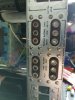
Here ya go, gadg, inside and out. What are you thinking? I poked around with a plastic "poker" and nothing made any kind of sound. I did check values of parts; don't recall if I checked all related parts. I believe I'm on to something, just not sure what.

The inside picture, from top down, right channel closest to you, the jacks are:
tape head
phono low
phono high
space
rcrdr out
tape mon
aux
metal plate

What about those reverb jacks? Would I damage anything if I removed the inserts for a minute while the unit is powered on? I haven't done anything with them and now I'm suspicious.

EDIT: I found something suspicious. I'm doing continuity testing. I attach one probe to the dark brown wire at selector switch (one of the input jack leads, don't know what it's for). I set the selector on FM STEREO which should mean that no input jacks are active (with power off). Then with the other probe I touch all the pins of all the input jacks. Guess what? The ONLY pin to have continuity is the PHONO LOW input jack for the LEFT channel ! In post 248 it is the LEFT channel that cannot be shorted. That tells me there's a short in that lead. Make sense?

All those wires go through a metal tube so I cannot see the condition of the insulation on those leads.

Never mind...That dark brown lead goes to the PHONO LOW left channel so of course I'm testing continuity on the same lead at both ends. Nothing suspicious after all.
 

Attachments

  • 0612200747.jpg
    0612200747.jpg
    162 KB · Views: 9
  • 0612200747a.jpg
    0612200747a.jpg
    104 KB · Views: 9
Last edited:
Thorne,

I wouldn't think anything inside those shield conduits would be shorted to it, but you could check the wire to ground to see if there is continuity. There shouldn't be a dead short to ground on those wires - otherwise why shield them?
 
I was just thinking maybe a ground wire off or something touching where it should not be. Not sure if that shield is meant to be soldered to the chassis, but if it is make sure its still solid. I've never been into one of these so I'm not intimately familiar with what it ought to look like but nothing sticks out as being obviously tampered with to me.
 
Gadget,

In general the shields are soldered to the chassis/ground. A quick check of pictures of someone else's unit would verify. Now it might be possible that someone soldered at additional locations along the conduit and that might create ground loops. Not sure that would be his problem, but it's a thought.

The difference in behavior at the jacks when using shorting plugs is a clue IMHO. I just don't know what that clue means.
 
Loose jacks on the phenolic. Had the same basic problems on my X-101-B with phono, and my Sansui 1000A. Tightened up centers and resoldered ground points. It may or may not work but it's worth a shot. On the Sansui, I replaced all the jacks.
 
Thanks, Guys. Yeah, there's definitely a clue there. Something for me to ponder. The plastic in the jacks (is that the "phenolic"? the insulator?) is loose in almost all of them i.e. I can turn the plastic rings easily.

One thing I haven't tried is plugging something in to ALL the input jacks. Maybe that will provide another clue. But now that the power section is "out of the way," I'm ready to dig into this again.
 
Last edited:
Larry - Is the "phenolic" the white plastic insulation into which the plug's pin is inserted, or is it the dark brown wafer-like material that holds all the input jacks in place?

And how does one replace all that given that it looks like rivets hold it all together?
 
Last edited:
Thorne,

Phenolic is the brown wafer the RCA's sit on. Is Larry indicating that it is becoming conductive in some way?
 
Tim - What Larry said is in post 254, 4 posts up (in case you want to read his complete post). He suggested my issue may be "loose jacks." He said he tightened their centers and resoldered their grounds. On another unit he replaced all the jacks. That's why I asked 2 posts up how one does that since rivets hold everything in place. I'm carefully looking at all the jacks and the connected components.

UPDATE: When I wiggle a shorting plug in the right channel PHONO LOW with the selector switch on PHONO STEREO, the hum moves from both channels to left channel only. So I believe I have to fix that jack first.
 
Last edited:
The phono jacks get the most "use and abuse" of all of the RCA jacks. I've noticed on all of the Fishers (both tube and S.S.) that I've handled in my grubby little mitts, that the PHONO jacks are loose in the center (white plastic or ceramic on early stuff).

The old jacks are crimped to the phenolic (ok, hardboard with resin) and work loose over the years. The Phenolic is riveted to the chassis and forms the ground points for the jacks. The plastic or ceramic bushing (white in the center) gets loose and with all this looseness, it's like a VW bug screwing the Holland Tunnel...The plug either doesn't make contact, or makes poor contact with center contact, or worst case, it shorts to the case. If you feel ambitious get some smoked lexan or plex. Cut to size, drill all holes, and install screw in jacks. Tie all grounds to one point, and the signal lead to center contact. You have to remove the phenolic to tighten up the jacks, so why not just replace them with better grade parts.
 
"like a VW bug screwing the Holland Tunnel."... Definitely a candidate for "Guinness's Book of Best Metaphors". :rflmao:

I tightened the jacks with a needle-nose which helped but still that right-channel PHONO LOW jack is troublesome. Yeah, some surgery seems required. Dr. Thorne to the rescue?

UPDATE: I traced 6 leads from input jacks to selector switch:

AUX right channel = WHT/GRN : main and shield connected at both ends.
AUX left = BLK/GRN : main and shield connected at both ends.
TAPE MON right = WHT/RED : main connected at both ends; shield at jack only.
TAPE MON left = BLK/RED : main connected at both ends; shield at jack only.
RCRDR OUT right = WHT/ORG : main connected at both ends; shield at jack only.
RCRDR OUT left = BLK/ORG : main connected at both ends; shield at jack only.

It's interesting that AUX has no hum and is the only pair of leads with both wires (main and shield) connected at both ends. I doubt I can conclude that all other leads should be connected the same way (shield at both ends). Besides, the above leads have 2 wires. The PHONO leads are a single wire. The jack's ground (shield) is connected to the pin via resistor and I wouldn't know to where I could attach a wire at the selector switch side. So no conclusions so far.
 
Last edited:
Back
Top Bottom