

You are using an out of date browser. It may not display this or other websites correctly.
You should upgrade or use an alternative browser.
You should upgrade or use an alternative browser.
Need help getting rid of hum
- Thread starter thornev
- Start date

thornev
Super Member
I was afraid of this... From pulling the SDS board out so many times, the wire connections weaken each time. One of the wires came completely loose inside the insulation. The wiring job on this SDS board is not the greatest. I think I should strengthen all the connections before my next test. Back later.
OMG - I just got a 430v shock. How in the world do I drain those e-caps on the SDS board ???? My head is spinning. Ow that hurt. I have a special tool for draining, but usually I have exposed leads with which to drain. But in this case I have to strip insulation to get to the wire. Catch 22. When I get my head back together I'll figure something out. Rubber gloves for one thing !
OMG - I just got a 430v shock. How in the world do I drain those e-caps on the SDS board ???? My head is spinning. Ow that hurt. I have a special tool for draining, but usually I have exposed leads with which to drain. But in this case I have to strip insulation to get to the wire. Catch 22. When I get my head back together I'll figure something out. Rubber gloves for one thing !
Last edited:
thornev
Super Member
Fixed the broken wire. Got sound back... including the hum.  Nothing changed. I hear both a 120Hz and a 60Hz hum and 60Hz gets louder when I move my hand close to input jack wires. The TAPE HEAD hum is definitely louder. AND the TAPE HEAD hum is more 60Hz. Interesting. Gonna keep lookin'.
Nothing changed. I hear both a 120Hz and a 60Hz hum and 60Hz gets louder when I move my hand close to input jack wires. The TAPE HEAD hum is definitely louder. AND the TAPE HEAD hum is more 60Hz. Interesting. Gonna keep lookin'.
Last edited:

see if the ground side connections on the tape and phono jacks are good. Not sure how Fisher did it, maybe its got a dedicated ground, maybe its just to chassis, but make sure whatever it is works. If there is an open ground you'll get 60hz. Kinda sounds like there is since moving your hand near the jacks makes it pick up more 60hz.
thornev
Super Member
gadg... By "good" you mean if there is continuity between the ground at the jacks and the chassis ground? I'll have to check all jacks with the selector switch in all positions because Fisher designed the switch to short out those + pins that are not selected by the switch.
EDIT: The outer part of all input jacks do indeed have continuity with chassis. I believe that's the test you suggested. The + pins may or may not have continuity and changes per the Fisher design I mention above. I also checked the reverb IN/OUT jacks - all good.
The hand response is curious. It's as if a shield is not working or missing or is not properly disconnected on one side.
EDIT: The outer part of all input jacks do indeed have continuity with chassis. I believe that's the test you suggested. The + pins may or may not have continuity and changes per the Fisher design I mention above. I also checked the reverb IN/OUT jacks - all good.
The hand response is curious. It's as if a shield is not working or missing or is not properly disconnected on one side.
Last edited:

Tim D
Super Member
Thorne,
Not to put words in his mouth, but I think he means the R13, R17, R21, and R23 are at the control grids of the two halves of the phono/tape preamp dual triode tubes. I think he's suggesting that those resistors probably land on terminals that go to the chassis ground. Check the riveted connections are a dead short with absolutely zero resistance and maybe solder the base of that terminal strip at the rivet to the chassis if not absolutely zero ohms. You might want to check those resistors too to see if they are way out of spec. (Some resistors you can check in-circuit - some you can't give it a try and see. If they read high then the resistor is bad. If the resistor reads low that might mean it has a parallel path around the resistor and you would have to go to the extra step of lifting one end to re-measure it.)
Note that on my KX-200 someone went the extra step to solder all of those kinds of rivet connections on terminal strips. (Not sure if Fisher did that, but I suspect a previous owner did mine.)
Not to put words in his mouth, but I think he means the R13, R17, R21, and R23 are at the control grids of the two halves of the phono/tape preamp dual triode tubes. I think he's suggesting that those resistors probably land on terminals that go to the chassis ground. Check the riveted connections are a dead short with absolutely zero resistance and maybe solder the base of that terminal strip at the rivet to the chassis if not absolutely zero ohms. You might want to check those resistors too to see if they are way out of spec. (Some resistors you can check in-circuit - some you can't give it a try and see. If they read high then the resistor is bad. If the resistor reads low that might mean it has a parallel path around the resistor and you would have to go to the extra step of lifting one end to re-measure it.)
Note that on my KX-200 someone went the extra step to solder all of those kinds of rivet connections on terminal strips. (Not sure if Fisher did that, but I suspect a previous owner did mine.)
thornev
Super Member
EDIT: nvm...I found R17. But why "1/2" ???
Tim - I apparently do not have R17 (BRN-BLK-BLK) ! At least it's not in the same location relative to V17 as R13 is relative to V16. Where R17 should be is a green wire going to the selector switch and there is no 10-ohmer anywhere around there.
The schematic is interesting. For R17 it says "1/2 R17" and it SHOULD be in the same location relative to V17 as R13 is relative to V16 - hung off V17 pin 2 in series with R14 and R15. Trying to find other 1/2.
Still looking.
Tim - I apparently do not have R17 (BRN-BLK-BLK) ! At least it's not in the same location relative to V17 as R13 is relative to V16. Where R17 should be is a green wire going to the selector switch and there is no 10-ohmer anywhere around there.
The schematic is interesting. For R17 it says "1/2 R17" and it SHOULD be in the same location relative to V17 as R13 is relative to V16 - hung off V17 pin 2 in series with R14 and R15. Trying to find other 1/2.
Still looking.
Last edited:
thornev
Super Member
R14 is at pin 2 of V17. With selector on AUX, the tube side of R14 is NOT grounded. Its other side is grounded. Is that the expected behavior? I think so because R10 (V16 pin 2) is the same.
None of my grounds are dead zero. They are all 0.2 ohms. I believe that is probably a result of the multimeter, a Fluke 115.
None of my grounds are dead zero. They are all 0.2 ohms. I believe that is probably a result of the multimeter, a Fluke 115.
Tim D
Super Member
Odd that R17 isn't in your unit. Did you check the entire circuit from PC2 all the way back to the phono jack? It might be in the circuit but not necessarily located near V17 - maybe even in the control panel near the selector switch S1 and PC2. That might mean that R17 is at the front panel somewhere. Also, there is more than one schematic for the 500C, right? Do they all show R17?
Tim D
Super Member
Tim - See my EDIT at the top of post 210.
I have no idea what is the 1/2 R17.
 Maybe half watt? Is it fatter than the others?
Tim D
Super Member
Thorne,
An interesting point about R13 and R17 is it appears that it lifts the grounds for the phono and tape inputs above ground potential using R13 and R17 10 ohm resistors. I find that odd, but apparently that is their design. So if you measure the shield on the phono and tape inputs you should get a non-zero resistance to ground - maybe 10 ohms? (If you measure it - make sure there is no voltage on the system beforehand. Don't want to hurt your MM.)
An interesting point about R13 and R17 is it appears that it lifts the grounds for the phono and tape inputs above ground potential using R13 and R17 10 ohm resistors. I find that odd, but apparently that is their design. So if you measure the shield on the phono and tape inputs you should get a non-zero resistance to ground - maybe 10 ohms? (If you measure it - make sure there is no voltage on the system beforehand. Don't want to hurt your MM.)
thornev
Super Member
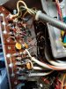
I don't know if this will help, but since we're focused on the input jacks, here's an image. The TAPE and PHONO jacks are the 3 pairs on top.
Also V16 and V17 though they are kinda blocked by those big a** PIO caps. Those parts attached to PEC PC1 is the RIAA mod.
Note that the only shielding for the PHONO and TAPE jack wires is that metal tube.
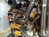
Also attached a pic of the RIAA mod before I installed them. I know it looks like the inner resistor is touching the cap wire, but it doesn't.
Also V16 and V17 though they are kinda blocked by those big a** PIO caps. Those parts attached to PEC PC1 is the RIAA mod.
Note that the only shielding for the PHONO and TAPE jack wires is that metal tube.
Also attached a pic of the RIAA mod before I installed them. I know it looks like the inner resistor is touching the cap wire, but it doesn't.
Attachments


Last edited:
