• The move to the new server is done. There are some software and database maintenance updates in process. This has us passing the hat around to help out. We appreciate any donations. Seriously, even a dollar helps. The payment page may be found here - https://www.audiokarma.org/support.html

Need to fix hum...(nordmende isabella E)

cam2000

New Member
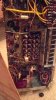
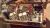
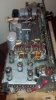
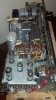
Hello. I picked up a great old tube amp/radio (nordmende isabella E), with a great old hum! I've been told to replace the electrolytic caps.

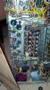
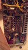
Does anyone know from looking at it which ones they are?
 

Attachments

  • IMG_20130715_174039_742.jpg
    IMG_20130715_174039_742.jpg
    22.6 KB · Views: 62
  • IMG_20130715_174027_311.jpg
    IMG_20130715_174027_311.jpg
    21.5 KB · Views: 33
  • IMG_20130715_172743_663.jpg
    IMG_20130715_172743_663.jpg
    20.4 KB · Views: 67
  • IMG_20130715_172714_598.jpg
    IMG_20130715_172714_598.jpg
    18.4 KB · Views: 47
  • IMG_20130715_172541_442.jpg
    IMG_20130715_172541_442.jpg
    14.5 KB · Views: 50
Register to hide this ad
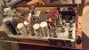
Those are some pretty small pictures. From here (with my great old eyes) I can only guess that the two tall outermost towers along the very back edge in the middle photo of the set shows the filter caps. One silver on the right-hand side, and the black on the left-hand side. Welcome to AudioKarma!
 
The hum is caused by AC passing thru the capacitors, which is bad
But the hum indicates that the amplifier is working, which is good

usually the caps to replace are the big silver can caps
They hold multiple capacitors
You can't find direct replacements (most of the time)

The easiest way is to get individual caps and mount them under the chassis

Just google replacing electrolytic capacitors
Join radiomuseum for the schematic
Some of my first work was on these Eurocentric radios
Normende is a great find

yeah, those thumbnail size pictures...not too good
 
Last edited:
If you look at the tall 'column' multi-section capacitors mentioned in post #2, you should see some markings with numbers of uF or MF and voltages. The voltages are those which the radio transformer puts out, so these capacitors are likely to rated for around 300V, 400V or even 500V.

If you take some bigger closeup pics, we can help you identify them and advise on how to replace them. Have you done any soldering before and do you have a multimeter?
 
Hello. I picked up a great old tube amp/radio (nordmende isabella E), with a great old hum! I've been told to replace the electrolytic caps.

Does anyone know from looking at it which ones they are?

Hi, and welcome...
The pic is kinda small, but it looks like the round cans on top of the chassis in the middle pic,,, one looks like aluminum, and a black cardboard covered one, the ones with holes look like tube covers,,, there may be others under the chassis... Larger pics will help confirm...
I just worked on a Freed tuner chassis, you can see where I put the replacements, under the chassis...

Regards,
John
 
Last edited:
I've got a 63 Isabella. WHAT A ROYAL PITA to Recap. Worse than a SANSUI 1000A!!!!

One of those towers (I believe it's the right most one next to the transformer is a Selenium Stack rectifier, not a power cap. You can make a diode bridge, and replace the selenium can with the bridge. 90% of the caps are on the underside and buried below other components.

If you've never done an amp/receiver before, this is NOT one to start with!

Larry
 
All German radios are a pain to work on, but they work really well once done. The filter caps as mentioned are the silver cans, and its got a selenium rectifier in that black can. Check the voltage output with the new caps to see if its in spec. If it is, you can leave it alone if you want. If the voltage is low, replace it with silicon rectifiers and probably a 100 ohm resistor to drop the voltage back down. If its got any paper caps, replace them. If they are plastic bodied, chances are fair that they are fine.

Not sure I'd totally disagree about not redoing one of these as a first project but if you have some experience soldering and working in tight areas you'll do OK.
 
If you do dig into the capacitors underneath, and you may have to replace them, I suggest that you clip the leads close to the old caps and attach the replacements to these leads. That's how I did it on a vintage receiver of the same era. It's much easier than desoldering wires and disturbing other connections.

If you've not done this before, note that some capacitors are electrolytic and MUST be orientated correctly with polarity. This applies to the cans and some others which will have one side marked ++ or --. Others can be mounted either way.
 
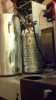
All great advice. Thank you. Here are the larger pictures. Sorry about the thumbnails. An error.

So, to be clear, the towers contain several caps, which in parallel, or series create and overall capacitance?
The towers themselves would be impossible to source, but several modern caps would to the job?
And these can either be housed back in the towers, or somewhere else?

I don't have much soldering experience, but I would attempt it with a friend who does.

I've read the caps need to be tested at high voltage to show how they are reacting at that voltage (ie. they are not linear, so will not necessarily read correctly at low voltages).

 

Attachments

  • IMG_20130715_172714_598.jpg
    IMG_20130715_172714_598.jpg
    59.8 KB · Views: 33
  • IMG_20130715_172541_442.jpg
    IMG_20130715_172541_442.jpg
    54.2 KB · Views: 24
  • IMG_20130715_174039_742.jpg
    IMG_20130715_174039_742.jpg
    74.9 KB · Views: 30
  • IMG_20130715_174027_311.jpg
    IMG_20130715_174027_311.jpg
    83.6 KB · Views: 27
  • IMG_20130715_172743_663.jpg
    IMG_20130715_172743_663.jpg
    78.4 KB · Views: 40
I've got a 63 Isabella. WHAT A ROYAL PITA to Recap. Worse than a SANSUI 1000A!!!!

One of those towers (I believe it's the right most one next to the transformer is a Selenium Stack rectifier, not a power cap. You can make a diode bridge, and replace the selenium can with the bridge. 90% of the caps are on the underside and buried below other components.

If you've never done an amp/receiver before, this is NOT one to start with!

Larry


Are you saying it's probable the Selenium Stack would need replacing as well?
 
Are you saying it's probable the Selenium Stack would need replacing as well?

Probably. Replacing it with a bridge rectifier is not difficult or expensive but may raise the B+ voltage. As gadget73 says.

The caps in the cans are not usually in parallel. The can is is a way of placing a number of high voltage caps in a compact place. In series, they often have resistors between them to aid smoothing and/or to drop the voltage for other places in the circuit where power is needed.

You need to get the schematic (from that radio museum site) and then just work systematically through the process of replacing each one, observing polarity when the caps have polarity markings.

Before starting, it might be wise to disconnect the power transformer from the rectifier and check that it is working.

But, it probably is, and it's just a matter of patiently replacing all the caps, except the small value ceramic ones. These are general comments. Larryderouin may be able to give you specific tips.
 
Congrats! Great find! If you don't know it's best not to run it without a load or speakers when testing etc. as you risk the output transformers. It doesn't hurt to test resistors (they usually go high) when rebuilding along with cleaning tube sockets & pins.

Also it's a good idea to take many detailed pics & replace only one or two caps etc. at a time and then test it.
 
+1 to Shadowdog's last comment. In your first post, you say you've already powered it up. Did you get audio, with a hum? If so, doing a bit at a time will help you keep track of your changes.

Can you trace the lead from the selenium rectifier to the can caps and then tell us what the values on the can are?
 
Looks like 2 can caps, the tallest one to the right near the output tubes and a shorter one behind it. Its got the little "belly button" on top. The tall one appears to be a 2 capacitor can. The can is common negative, and it has 2 positive leads. The short one looks to be a single capacitor.

The selenium rectifier may be perfectly fine. Check it's output voltage against the schematic. If the voltage is where it should be, I'd vote for leaving it alone.
 
I don't have any specific tips other than having a lot of patience. This is NOT a BEGINNER's unit to work on. On a scale of 1-5 for difficulty, I'd give it a 4.5. It's extremely tight inside the chassis. SMALL form factor caps are called for, although I used a fair amount of IIRC CDE Axials, they weren't the best for shoehorning into it. The only thing I clearly remember about it is it took me 4-5 times longer to recap than my 1000A. I paralleled 2 1n4007's for the rectifier (in the cap) and it worked out well. No need for a full bridge.
 
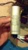
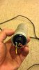
Hello. I got into the cap towers as mentioned. You can see here the values written on them. Still a tad bamboozling for me.
I think I will leave the towers just sitting there, and put new ones under the chassy, as suggested...
 

Attachments

  • IMG_20130722_181938_831.jpg
    IMG_20130722_181938_831.jpg
    40.9 KB · Views: 20
  • IMG_20130722_182012_413.jpg
    IMG_20130722_182012_413.jpg
    41.9 KB · Views: 21
  • IMG_20130722_182024_425.jpg
    IMG_20130722_182024_425.jpg
    37.5 KB · Views: 17
Okay the smaller electrolytic is a 50uF cap rated at 350-385V. Get a 47uF (or 50uF) electrolytic capacitor rated at 450V or higher. The can casing is negative and the terminal is positive. This could be mounted underneath.

The bigger can has two 100uF capacitors rated at 350-385V in it. Get two 100uF electrolytics rated at 450V or higher. Again the can casing is negative (common to both caps) and the two terminals are both positive. Good quality modern replacements are available, e.g. F&T in Germany. The advantage of that is it would make replacing this easy in the limited space you have.

What you need could be ordered from here: http://www.thetubestore.com/Capacitors/F-T (can at $22 and individual cap at $10). Both of these are rated at 500V which is good. It would also be worth ordering a new capacitor clamp for the replacement can from them at $2.

You did take pictures of these caps were connected before you removed them? If not, take pics or write down notes of which wire went where now. And, when you get them, please remember to OBSERVE POLARITY with these high voltage electrolytics. :)
 
The way the Germans did their markings is to provide steady working voltage (350) and a surge voltage (385) that it could deal with for a brief amount of time. The voltage immediately after switching the unit on will be at the highest until the tubes start to conduct and draw the supply voltage down a bit. Replace them with 400 or 450v caps and you're good to go.
 
Back
Top Bottom